Device for controlling and/or regulating the fuel quantity supplied to an internal combustion engine

a technology of internal combustion engine and fuel quantity, which is applied in the direction of electric control, machines/engines, instruments, etc., can solve the problems of high production cost, inability to level out aging effects, and only inadequate leveling, so as to improve operating behavior and efficiency, influence the quantity profile of fuel injection accurately, and control even more accurately

Inactive Publication Date: 2006-08-29
DAIMLER AG
View PDF10 Cites 7 Cited by
  • Summary
  • Abstract
  • Description
  • Claims
  • Application Information

AI Technical Summary

Benefits of technology

[0008]Using a miniaturized mass flow sensor and control unit, the fuel injection quantity and also the fuel injection quantity profile can be influenced accurately. As a result, combustion in the internal combustion engine can be controlled even more accurately and therefore an improvement in the operating behavior and in efficiency, and at the same time a reduction of harmful exhaust gases, can be achieved. The arrangement of the mass flow sensor in the fuel inflow line is particularly advantageous in terms of the available construction space.
[0009]If a highly dynamic actuating unit is used for the nozzle needle, then the sensor data detected during an injection operation can preferably also be used for influencing the current injection operation. If the dynamics of the actuator used are not sufficient for this purpose, then the sensor data can be used for determination of preset values for one or more subsequent injections. Using such improved preset values, the outlay in regulating terms during the next injections can be reduced.
[0011]The use of an adaptor piece in the fuel inflow line with an integrated mass flow sensor has the advantage of simplified assembly. Moreover, such adaptor pieces can be exchanged or existing injection systems retrofitted in a very simple way.

Problems solved by technology

At the same time, the injection nozzles are subject to the highest possible requirements as to manufacturing tolerances, thus leading to high production costs.
Moreover, aging effects cannot be leveled out or can be leveled out only inadequately by the characteristic maps.

Method used


Image

  • Device for controlling and/or regulating the fuel quantity supplied to an internal combustion engine
  • Device for controlling and/or regulating the fuel quantity supplied to an internal combustion engine

Examples


Embodiment Construction

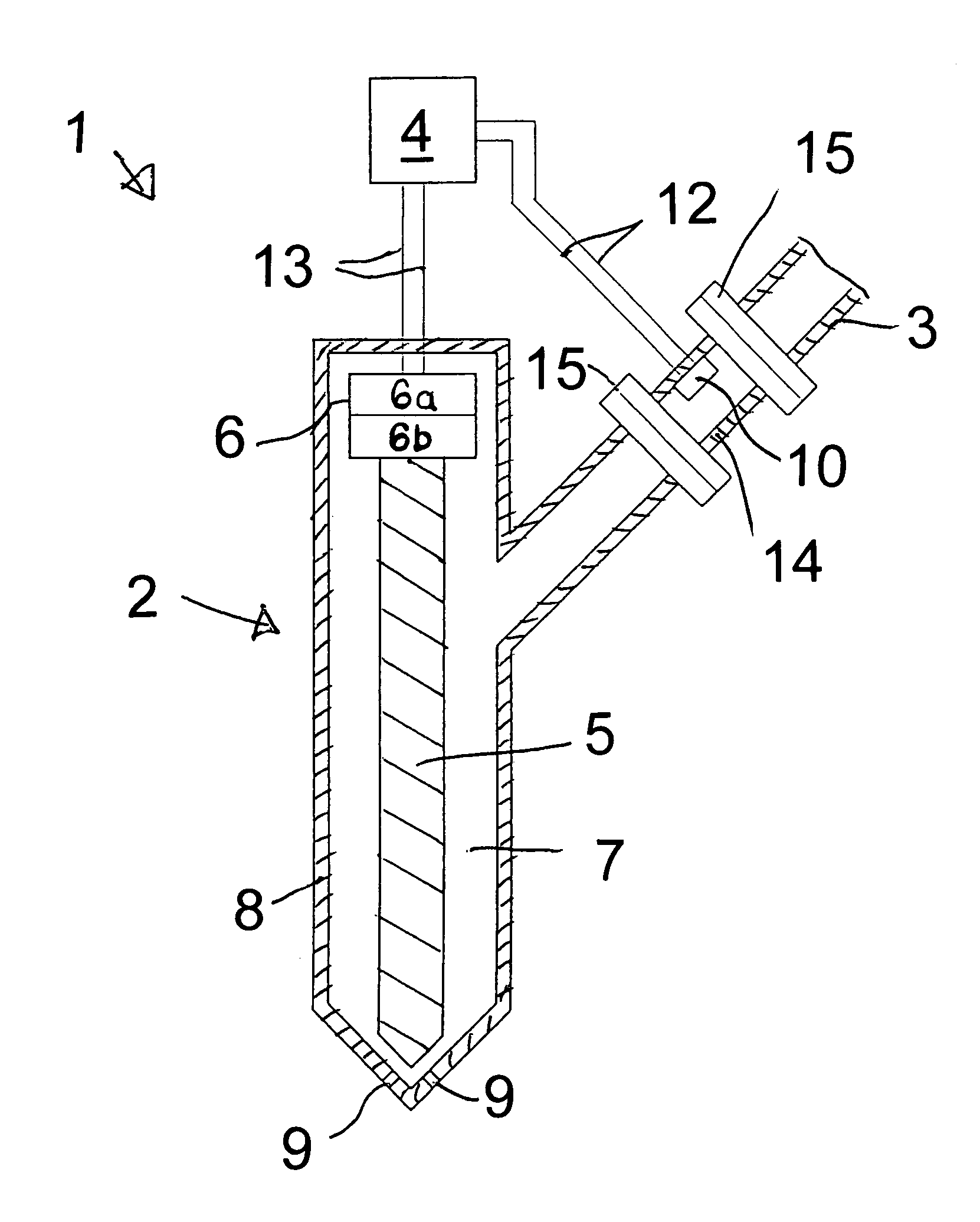
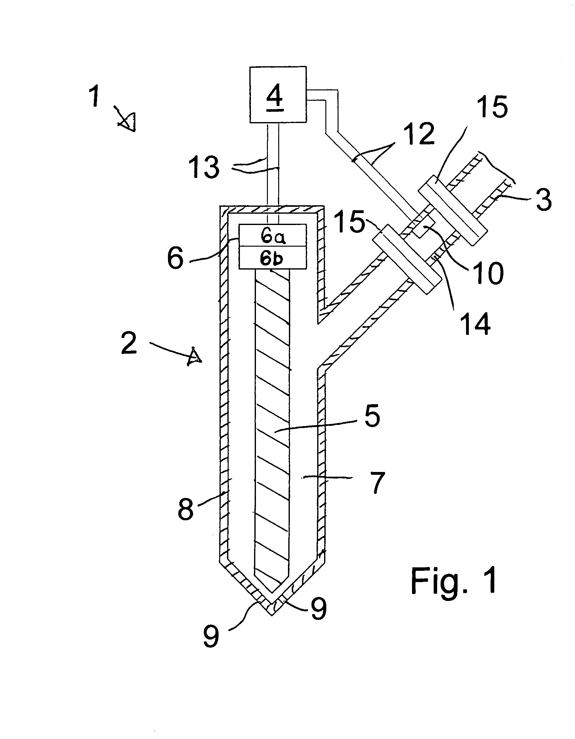
[0014]The device, identified as a whole by 1, for controlling and / or regulating the fuel quantity supplied to an internal combustion engine, not illustrated in detail, has an injection nozzle 2, a fuel inflow line 3 and a control unit 4. The injection nozzle 2, known per se and therefore illustrated only diagrammatically, has a nozzle needle 5 and an associated actuator 6 for actuating the nozzle needle 5. The actuator 6 may, if required, be of two-part design, one part 6a of the actuator 6 serving for the rough adjustment of the nozzle needle 5 and therefore for the rough setting of the fuel quantity, while the other part 6b of the actuator 6 serves for the highly dynamic adjustment of the nozzle needle 5 and therefore for the fine tuning of the fuel quantity.

[0015]The fuel inflow line 3 serves for the supply of fuel from a fuel tank, not illustrated, or from a fuel pump, not illustrated, into an annular space 7 between the nozzle needle 5 and a housing 8 of the injection nozzle 2....


PUM


Abstract

In a device for controlling the fuel quantity supplied to an internal combustion engine via a fuel supply line and an injection nozzle which includes a nozzle needle and an actuator for controlling the position of the nozzle needle, wherein a sensor for the detection of injection parameters is provided which supplies injection parameter data to a control unit for determining, on the basis of the sensor data, control parameters for the actuator of the injection nozzle, the sensor is a mass flow sensor arranged in the fuel supply line.

Description

[0001]This is a Continuation-in-Part Application of International Application PCT / EP2003 / 011483 filed Oct. 16, 2003 and claiming the priority of German Application 102 53 297.4 filed Nov. 15, 2002.BACKGROUND OF THE INVENTION[0002]The invention relates to a device for controlling the fuel quantity supplied to an internal combustion engine, including an injection nozzle needle and means for controlling the position of the valve needle and a sensor for determining the injection parameters.[0003]An accurate metering of the injection of fuel to an internal combustion engine, in particular in the pilot quantity range of 1 mm3, makes it possible to influence exactly the subsequent combustion processes dependent on this injection, for example, an accurate control of combustion to achieve high efficiencies, at the same time with low pollutant values and noise generation, or else the compensation of aging effects. For this purpose, characteristic maps have hitherto been filed, which contain c...

Claims


Application Information

Patent Timeline
Patent Type & Authority Patents(United States)
IPC IPC(8): F02D41/34F02M61/16F02D41/30F02M51/06F02M55/02F02M65/00
CPCF02M65/002F02M61/16F02M51/0603F02M55/02F02M2200/24F02D41/3005F02D2200/0614
Inventor RENNER, GREGORSCHMID, ULRICHSOMMERER, WINFRIED
Owner DAIMLER AG
Why Eureka
Try Eureka