Method and apparatus for assembling a vehicle wheel

a technology for vehicle wheels and components, applied in the direction of transportation and packaging, papermaking, other domestic articles, etc., can solve the problems of limiting the ability of adhesive tape to reliably adhere the overlay to the wheel, prohibiting the use of such adhesive tapes in mass production, and affecting the economic and reliable

Active Publication Date: 2006-08-29
LACKS INDUSTRIES INC
View PDF12 Cites 21 Cited by
  • Summary
  • Abstract
  • Description
  • Claims
  • Application Information

AI Technical Summary

Benefits of technology

[0023]It is another object that such a method and apparatus is economical and reliable.
[0024]It is yet another object that such a method and apparatus provide a wheel cover permanently attached to a wheel without degrading the structural integrity of either component.

Problems solved by technology

), the cost of such adhesive tapes is generally prohibitive for use in mass production applications such as securing an overlay to a wheel.
Consequently, such applications are generally limited to the use of less expensive adhesive tapes that have relatively low maximum operating temperatures, necessitating that their placement be restricted to the radially outward surfaces of the wheel.
Unfortunately, doing so severely limits the adhesive tape's ability to reliably adhere the overlay to the wheel.
Further, the adhesive tape's thickness creates a void between the overlay and the wheel that can collect dirt and debris that may affect the balance of the wheel.
The overlay is configured to have variations in contours in a direction transverse to the axis of the wheel that exceed the variations in the rim and / or disc contour of the wheel, which variations would be extremely difficult and expensive, if not impossible, to stamp or draw in the disc of the wheel.
However, any excess polyurethane foam around the bolt holes or at the periphery of the assembly surrounding the axle hub will squeeze out if appropriate sealing provisions are not made.
Furthermore, wheels assembled according to the Derleth disclosure were very heavy due to the high density of the foam, and variation in localized foam density resulted in severe wheel imbalances.
Larger openings, such as turbine openings, would not be possible using the Derleth process without additional structure to seal the openings and prevent the foam material from escaping.
A drawback of the process according to Derleth is that excess foam mixture is required to ensure that the cavity between the cover and the wheel is completely filled, and subsequently any excess foam must be manually removed, which adds significant cost to the process.
A disadvantage with the Chase invention is that the wheel must be provided with a fill port through which the urethane foam is injected.
Accordingly, the Chase invention requires an additional process of machining the fill port in the wheel spider such that the overall process is more expensive.
Furthermore, the additional process for machining the fill port degrades the structural integrity of the wheel by removing material therefrom.
Unfortunately, the Joseph et al. invention is limited to applications wherein the wheel cover extends radially beyond the bolt hole circle in the wheel such that adhesive injected into the bolt hole of the wheel is introduced within the mold formed in part by the wheel and the wheel cover.
Additionally, in some applications the fixturing devices, locating devices, clamping systems, nesting systems and / or injection apparatus may limit accessibility to certain regions of the mold such that it would be desirable to have a variety of potential injection locations from which to choose.
From the above, it can be appreciated that the method and apparatus for attaching a wheel cover to a wheel are not fully optimized.

Method used


Image

  • Method and apparatus for assembling a vehicle wheel
  • Method and apparatus for assembling a vehicle wheel
  • Method and apparatus for assembling a vehicle wheel

Examples


Embodiment Construction

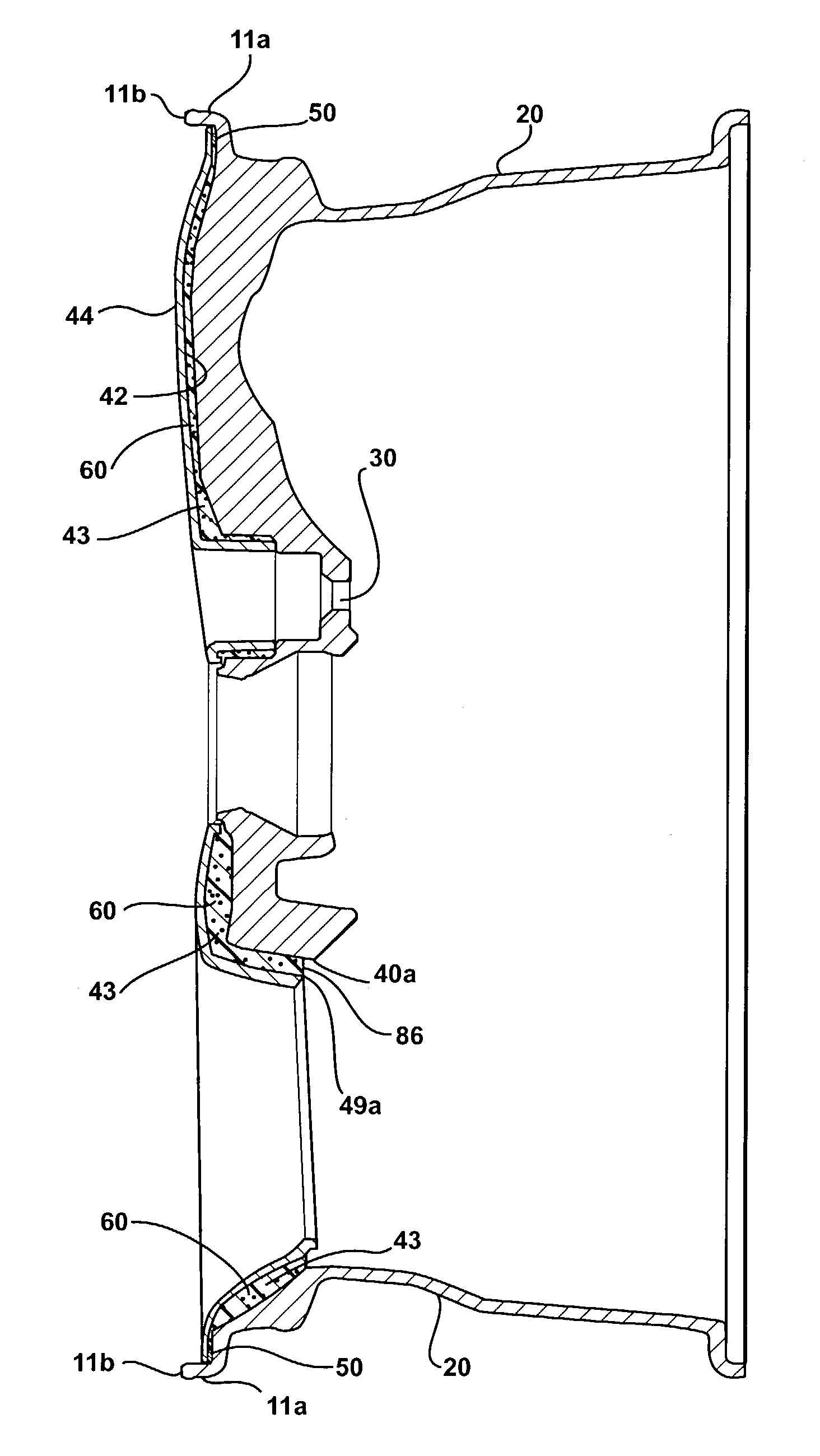
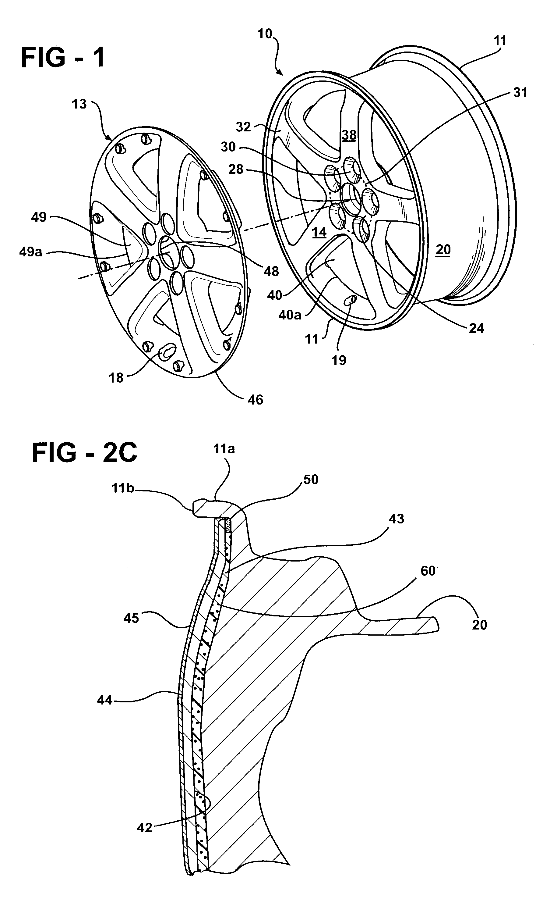
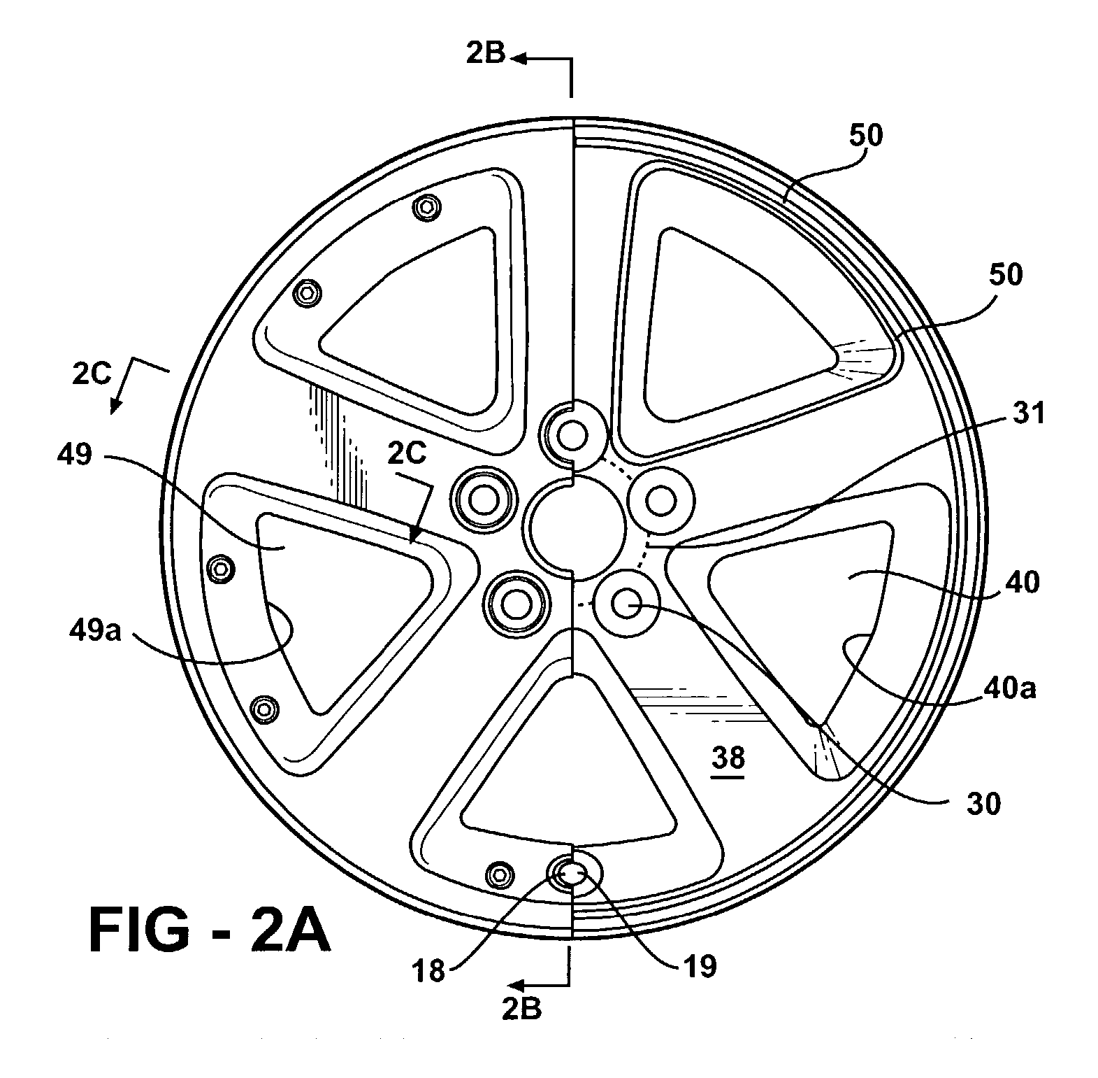
[0045]Referring now to the drawings, there is illustrated in FIG. 1 an exploded, perspective view of an automobile wheel 10. The wheel 10 is preferably a one piece aluminum wheel having a rim portion 11 and a disc portion 14. Together the disc portion 14 and the rim portion 11 define an outboard surface 32 of the wheel 10. A wheel cover or overlay 13 is attached to the wheel 10 as will be described hereinafter.

[0046]Although this invention is discussed in conjunction with the particular wheel 10 disclosed herein, it will be appreciated that the invention may be used with other types of wheel constructions. For example, the wheel can be a “bead seat attached” wheel (such as shown in FIG. 4 of U.S. Pat. No. 5,188,429 to Heck et al.), a “full faced” wheel (such as shown in FIG. 2 of U.S. Pat. No. 5,595,423, to Heck et al.), a “bimetal” wheel construction including an aluminum disc and a steel rim (such as shown in U.S. Pat. No. 5,421,642 to Wei et al.), a “modular wheel” construction i...


PUM

PropertyMeasurementUnit
temperatureaaaaaaaaaa
temperaturesaaaaaaaaaa
pressureaaaaaaaaaa

Abstract

A method and apparatus for attaching an ornamental overlay to a vehicle wheel by injecting adhesive foam through an aperture of the wheel and into a cavity formed between the wheel and the overlay. A first nest engages the outboard side of the wheel/overlay assembly to seal the inner periphery of the overlay, the valve stem opening of the overlay, the lug bolt receiving holes of the wheel, the pilot aperture of the wheel, and/or the valve stem opening of the wheel. A secondary nest engages the inboard side of the wheel/overlay assembly to seal the wheel apertures and a plurality of turbine openings in the overlay. A nozzle disposed within the secondary nest is adapted to inject the adhesive foam into the cavity through either a gap between the periphery of a wheel aperture and the periphery of a corresponding turbine opening in the overlay, through a straight or angled hole within a spoke, or through a groove within a spoke.

Description

CROSS-REFERENCES TO RELATED APPLICATIONS[0001]Not applicable.FEDERALLY SPONSORED RESEARCH OR DEVELOPMENT[0002]Not applicable.REFERENCE TO A MICROFICHE APPENDIX[0003]Not applicable.BACKGROUND OF THE INVENTION[0004]1. Field of the Invention[0005]The present invention relates to composite wheel assemblies for vehicles having an overlay permanently attached to a wheel, and particularly to an improved method and apparatus for permanently attaching an ornamental overlay to the wheel by injecting foam through a nest such that a separate pour opening in the wheel is not required.[0006]2. Description of the Related Art[0007]Decorative overlays are widely used to enhance the aesthetic appearance of automotive wheels. Numerous structural combinations of overlays with chrome-plated outboard surfaces have attracted great interest from vehicle manufacturers, because they are lightweight, aesthetically pleasing and offer designers complete flexibility with regard to the aesthetic effect that can b...

Claims


Application Information

Patent Timeline
Patent Type & Authority Patents(United States)
IPC IPC(8): B29C65/00B32B5/18B60B7/00B60B7/06B29C44/12B29C45/14B60B7/02
CPCB29C44/1233B60B7/18B60B7/0046B60B7/02B60B7/004B29C45/14467B29L2031/32
Inventor WOELFEL, JAMES A.WRASE, BRIAN C.
Owner LACKS INDUSTRIES INC
Why Eureka
Try Eureka