Laser machining apparatus

a technology of laser machining and machine, which is applied in the direction of soldering apparatus, manufacturing tools,auxillary welding devices, etc., can solve the problem of difficult control of machining, and achieve the effect of improving machining efficiency

Inactive Publication Date: 2006-08-29
HITACHI SEIKO LTD
View PDF8 Cites 11 Cited by
  • Summary
  • Abstract
  • Description
  • Claims
  • Application Information

AI Technical Summary

Benefits of technology

[0010]Accordingly, it is an object of the invention to solve the above-mentioned problems by providing a printed board machining apparatus whose restriction on the length of printed boards to be machined is small, that allows positioning of a sheet-like workpiece to be readily controlled and that is capable of improving the machining efficiency.
[0014]Because the inventive laser machining apparatus is capable of machining the plurality of lengthy printed boards whose length is equal to the moving stroke of the machining table concurrently by the plurality of laser condensing and positioning means, the restriction on the length of the printed board to be machined is small and the positioning of the sheet-like workpieces may be readily controlled. Still more, because the laser machining apparatus allows the number of times of positioning of the sheet-like workpieces on the machining table to be reduced, the machining efficiency may be improved. Furthermore, because the laser machining apparatus does not require changing the interval between the laser condensing and positioning means such as fθ lenses, its arrangement works may be facilitated.

Problems solved by technology

Therefore, it becomes difficult to control the machining.

Method used


Image

  • Laser machining apparatus
  • Laser machining apparatus
  • Laser machining apparatus

Examples


Embodiment Construction

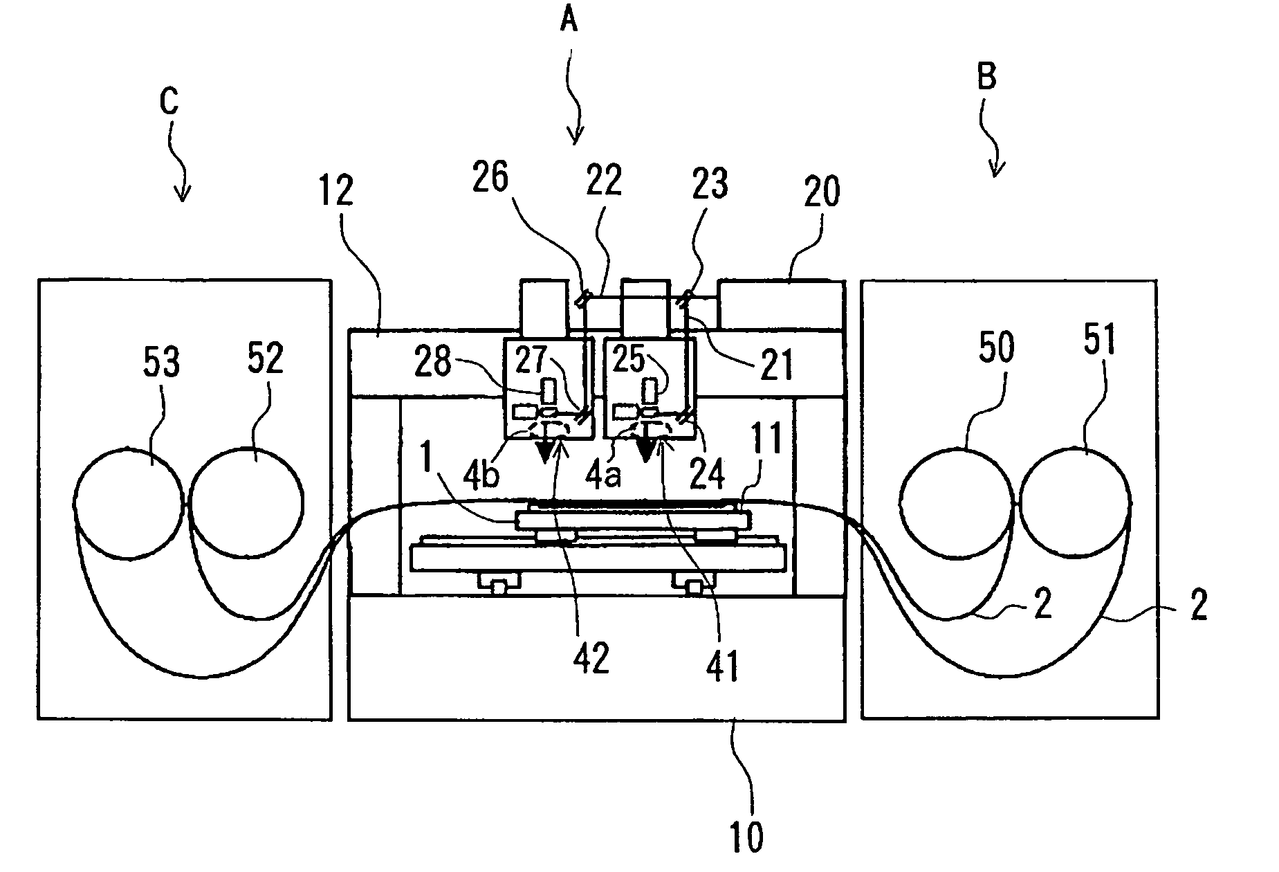
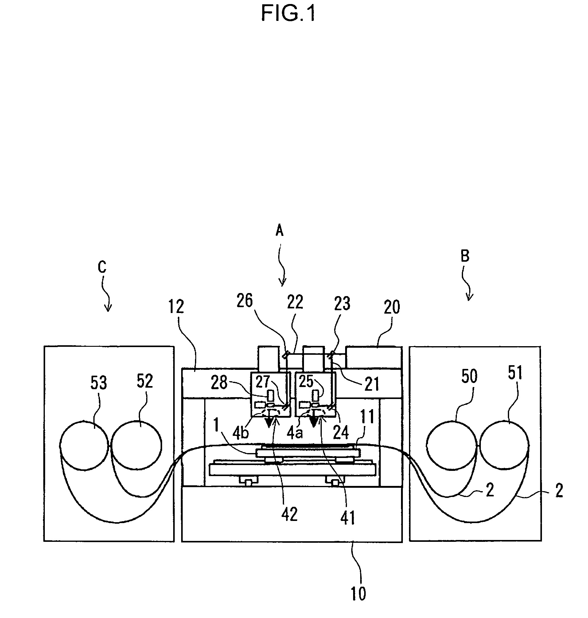
[0020]FIG. 1 is a structural view of a laser machining apparatus of the invention, FIG. 2 is a perspective view of a main part of the laser machining apparatus of the invention and FIGS. 3A and 3B are structural views of a machining table section, wherein FIG. 3A is a plan view thereof and FIG. 3B is a side section view thereof. The components identical to or having the same function with those in FIG. 4 will be denoted by the same reference characters and their overlapped explanation will be omitted here.

[0021]As shown in FIG. 1, an XY table 1 is disposed on a bed 10 of the laser machining apparatus A. The XY table 1 is movable on the bed 10 horizontally in X and Y directions. A machining table 11 is placed on the XY table 1. A gate-type column 12 is fixed to the bed 10 and a laser oscillator 20 is placed on the column 12. An acousto-optic modulator 23 for switching an optical path of a laser to a first optical path 21 or to a second optical path 22 is disposed on an optical axis o...


PUM

PropertyMeasurementUnit
areaaaaaaaaaaa
widthaaaaaaaaaa
distanceaaaaaaaaaa

Abstract

There is provided a printed board machining apparatus having fewer restrictions in terms of the length of printed boards to be machined, that can be readily controlled in positioning a sheet-like workpiece and that is capable of improving the machining efficiency. Plural sets of optical scanners and fθ lenses that compose laser condensing and positioning mechanisms are disposed apart in a width direction (X direction) orthogonal to a longitudinal direction (Y direction) of the sheet-like workpiece and two sheet-like workpieces are fixed on a machining table in parallel, and in the width direction to machine printed boards on the sheet-like workpieces The disposition of the fθ lenses allows the machining of the plurality of lengthy printed boards to be completed practically at the same time or at the same time without limiting the length of the printed boards to be machined.

Description

BACKGROUND OF THE INVENTION[0001]1. Field of the Invention[0002]The present invention relates to a laser machining apparatus having a machining table for fixing a part of a sheet-like workpiece thereon and laser condensing and positioning means, such as an fθ lens, for positioning and condensing a laser beam to the sheet-like workpiece to machine the sheet-like workpiece on the machining table by relatively moving the machining table and the laser condensing and positioning means, and when the machining of the workpiece ends, to move the sheet-like workpiece in the longitudinal direction to repeatedly machine a next machining area thereof.[0003]2. Description of Related Art[0004]FIG. 4 is a perspective view of a main part of a conventional laser machining apparatus for machining a sheet-like workpiece 2 while moving it in the longitudinal direction. The sheet-like workpiece 2 is fixed on the XY table 1 by means of a clamper not shown. The sheet-like workpiece 2 is fed from a supply ...

Claims


Application Information

Patent Timeline
Patent Type & Authority Patents(United States)
IPC IPC(8): B23K26/08B23K26/38B23K26/064B23K26/067B23K26/10B23K37/04B23K101/16B23K101/36H05K3/00
CPCB23K26/067B23K26/4025B23K26/0846B23K26/0853B23K26/10B23K26/381B23K37/0426H05K3/0026B23K26/0673B23K2201/16B23K2201/42H05K3/0008H05K3/0097H05K2203/0165H05K2203/082H05K2203/1545B23K26/382B23K2101/16B23K2101/42B23K2103/50
Inventor MASUDA, MITSURUMATSUMURA, KAORU
Owner HITACHI SEIKO LTD
Why Eureka
Try Eureka