Cathode ray tube having an improved shadow mask

Inactive Publication Date: 2006-08-29
MERIDIAN SOLAR & DISPLAY
View PDF12 Cites 6 Cited by
  • Summary
  • Abstract
  • Description
  • Claims
  • Application Information

AI Technical Summary

Benefits of technology

[0036]An object of the invention is to solve at least the above problems and/

Problems solved by technology

In other words, since the cathode ray tube is highly evacuated, it can be easily exploded by external impacts.
That is to say, when the curvature of the shadow mask 5 is distorted by the external impact F, the shadow mask cannot select colors of electron beams more effectively, and this causes deteriorations in picture quality of a cathode ray tube.
However, these traditional methods

Method used


Image

  • Cathode ray tube having an improved shadow mask
  • Cathode ray tube having an improved shadow mask
  • Cathode ray tube having an improved shadow mask

Examples


Embodiment Construction

[0059]The following detailed description will present a cathode ray tube according to a preferred embodiment of the invention in reference to the accompanying drawings.

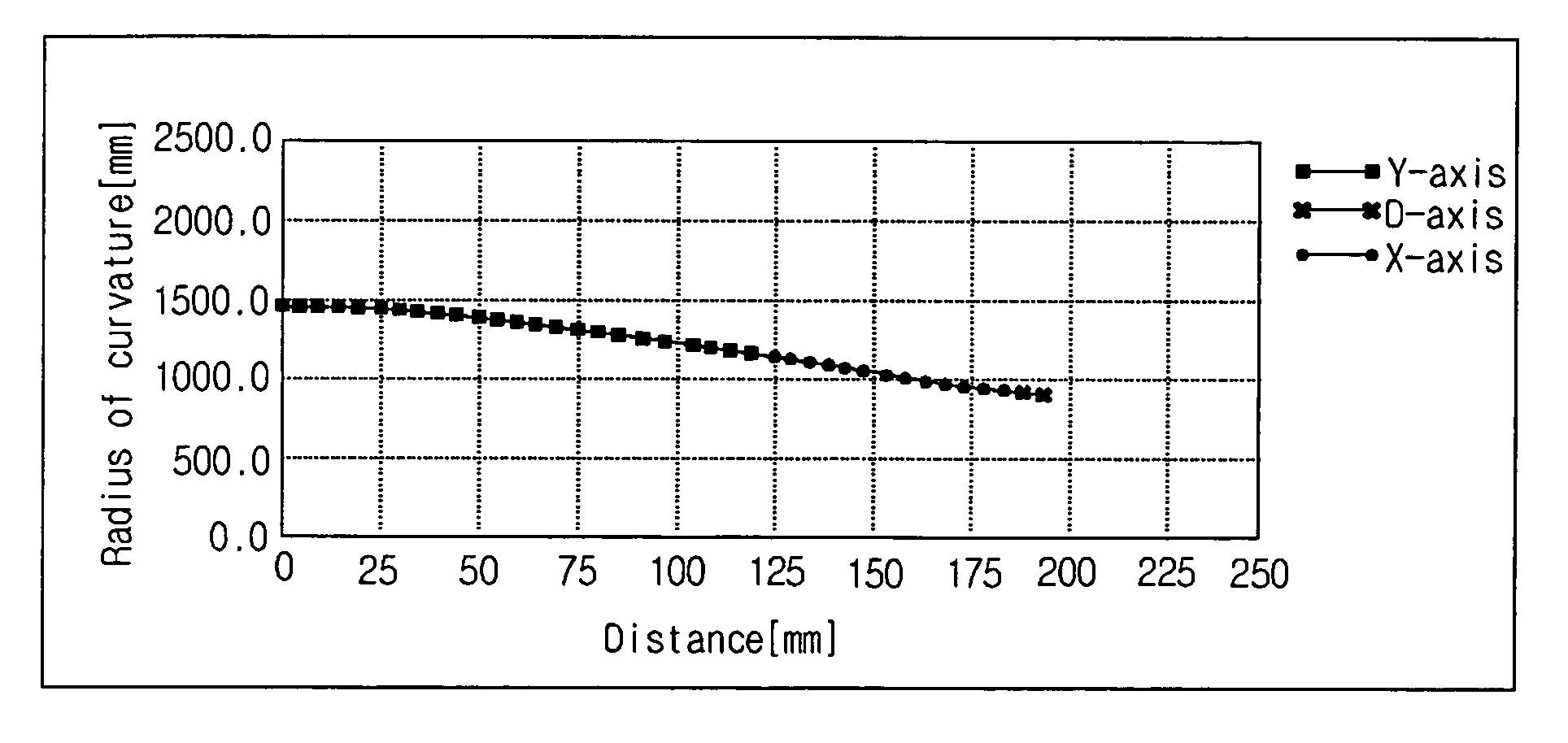
[0060]FIG. 7 illustrates radii of curvature of a shadow mask in a cathode ray tube according to an embodiment of the present invention, depending on a distance from a center of the shadow mask.

[0061]Referring to FIG. 7, the radius of curvature in a major-axis and diagonal-axis direction, respectively, of the shadow mask of the cathode ray tube of the invention is substantially same.

[0062]That is to say, as a distance from the center of the shadow mask is increased, the radius of curvature in the respective directions (major-axis, minor-axis and diagonal-axis directions) is not much different from one another, showing a substantially equal change.

[0063]Compared with the result obtained from a related art shadow mask in FIG. 6, the radius of curvature of the shadow mask of the embodiment of the present invention is shor...


PUM


Abstract

A cathode ray tube comprises a panel having a fluorescent formed on an inner surface thereof; a funnel connected to the panel; an electron gun housed in the funnel emitting electron beams; a deflection yoke for deflecting the electron beams in horizontal and vertical directions; a shadow mask for selecting colors of the electron beams; and a mask frame for supporting the shadow mask, in which an outer surface of the panel is substantially flat and an inner surface has a designated curvature, and a radius of curvature from a center of the shadow mask in a major-axis, minor-axis and diagonal-axis direction is substantially same.

Description

[0001]This Nonprovisional application claims priority under 35 U.S.C. § 119(a) on Patent Application No(s). 10-2003-0043290 filed in Korea on Jun. 30, 2003, the entire contents of which are hereby incorporated by reference.BACKGROUND OF THE INVENTION[0002]1. Field of the Invention[0003]The present invention relates to a cathode ray tube, more particularly, to a cathode ray tube including a shadow mask having an improved drop characteristic by adjusting a curvature thereof.[0004]2. Discussion of the Background Art[0005]FIG. 1 illustrates the structure of a related art color cathode ray tube.[0006]As depicted in FIG. 1, a panel 1 and a funnel 2 of the color cathode ray tube are sealed up (or connected) tightly together, so the inside of the cathode ray tube is generally in a vacuum state.[0007]To see the structure of the cathode ray tube, a fluorescent screen 3 with red (R), green (G) and blue (B) primary color phosphors (or fluorescent substances) is formed inside of the panel 1, and...

Claims


Application Information

Patent Timeline
IPC IPC(8): H01J29/81H01J29/07H01J29/86
CPCH01J29/07H01J2229/0788
Inventor KIM, YONG KUN
Owner MERIDIAN SOLAR & DISPLAY
Why Eureka
Try Eureka