Exposure method, exposure apparatus, and method for manufacturing device

a manufacturing method and exposure apparatus technology, applied in the field of exposure methods, can solve the problems of affecting peripheral systems, leaked permeable gas may affect peripheral systems, and affecting the control precision of interferometer systems, so as to prevent the leakage of permeable gas

Inactive Publication Date: 2006-08-29
NIKON CORP
View PDF16 Cites 146 Cited by
  • Summary
  • Abstract
  • Description
  • Claims
  • Application Information

AI Technical Summary

Benefits of technology

[0015]According to the exposure method, a light absorptive substance is removed from the optical path of the projection optical system by filling the exit portion of the projection optical system with the permeable gas with the substrate serving as a part of a partition. At the time of moving the substrate or replacing the substrate, an object is placed on the exit portion of the projection optical system so that the object becomes a part of the partition in place of the substrate. Accordingly, even at the time of moving or replacing the substrate, leakage of the permeable gas from the exit portion of the projection optical system is suppressed, so that the gas state in which the light absorptive substance on the exit portion of the projection optical system has been removed is maintained.
[0034]The device manufacturing method prevents reduction in control precision by leakage of the permeable gas in the exposure apparatus, thus making it possible to improve the pattern precision.

Problems solved by technology

As a substrate is frequently replaced in the exposure apparatus, however, it is difficult to eliminate the light absorptive substance from the space between the projection optical system and the substrate in the space of the optical path.
As the blown gas is likely to leak around a substrate according to the technique, however, the leaked permeable gas may affect peripheral system.
When a permeable gas enters the optical path of the interferometer, however, the difference between refractive indexes of a gas (air) which has been present on the interferometer optical path so far and the light absorptive substance changes the optical path length of the laser beam, which may lower the control precision of the interferometer system.
When a substrate is placed on the exit portion of the projection optical system, the substrate becomes a part of the partition to suppress the gas leakage, but when the substrate moves or the substrate is replaced, at least a part of the substrate which becomes the partition comes off the exit portion of the projection optical system, so that the gas state on the exit portion of the projection optical system is not kept and the gas leakage is likely to occur.

Method used


Image

  • Exposure method, exposure apparatus, and method for manufacturing device
  • Exposure method, exposure apparatus, and method for manufacturing device
  • Exposure method, exposure apparatus, and method for manufacturing device

Examples


first embodiment

[0049]an exposure apparatus according to the invention will be described below with reference to the accompanying drawings. In the embodiment, the invention is adapted to a step and scan type projection exposure apparatus which uses vacuum ultraviolet rays as an exposure energy beam. It is to be noted that the invention is not limited to the following individual embodiments, and, for example, the components of these embodiments may be combined adequately.

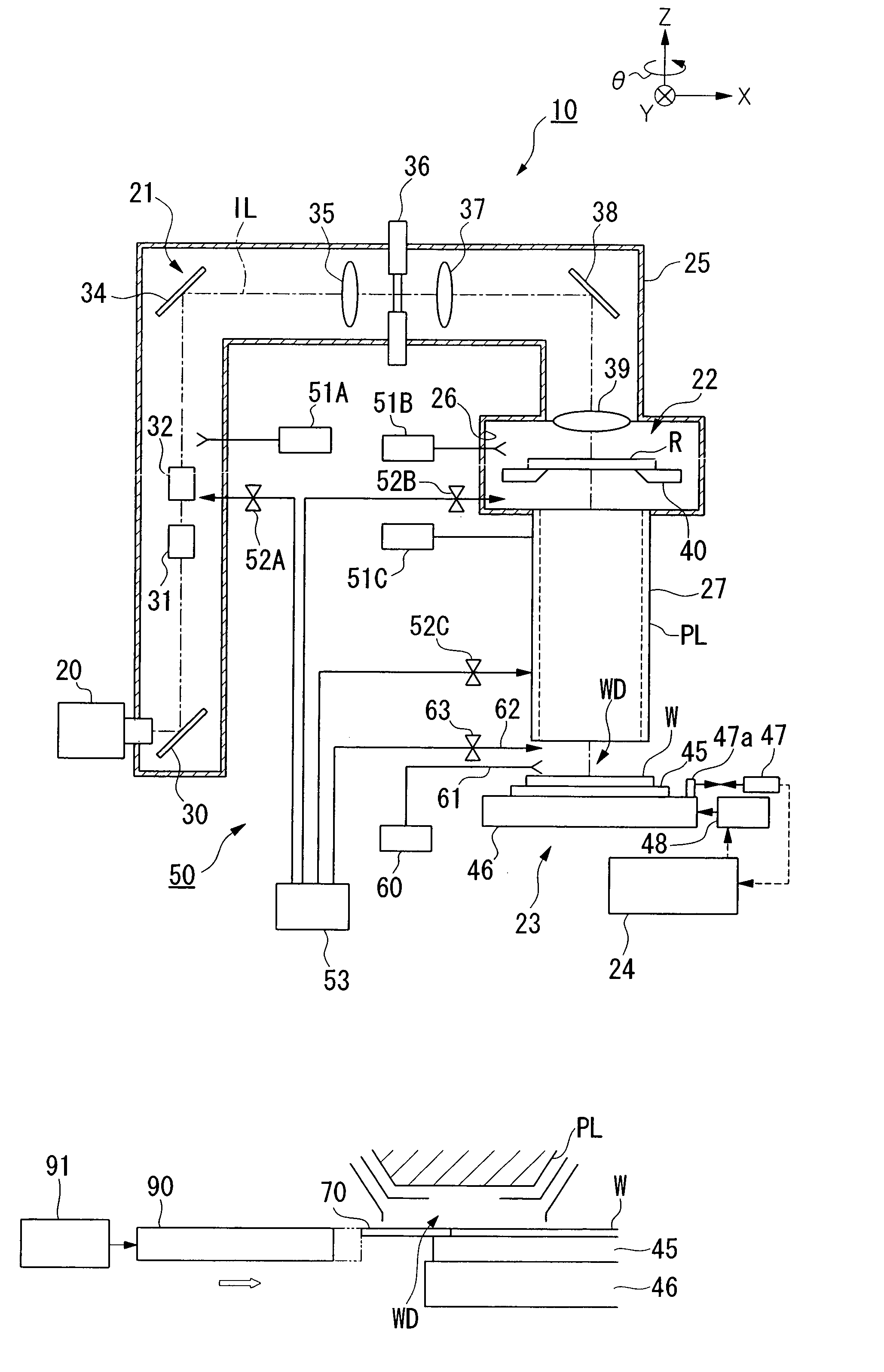
[0050]FIG. 1 is a partly cutaway structural diagram illustrating the schematic structure of an exposure apparatus 10 according to the embodiment, and in FIG. 1, the mechanism portion of the exposure apparatus of the embodiment is roughly separated into an illumination optical system 21, a reticle manipulation section 22, a projection optical system PL and a wafer manipulation section 23. The illumination optical system 21, the reticle manipulation section 22 and the projection optical system PL are respectively accommodated in an il...

second embodiment

[0068]FIG. 6 illustrates the exposure apparatus according to the invention, and the exposure apparatus of the embodiment has an opening / closing member 80, which opens and closes the gas supply port 65 in the gas supply / discharge system 50, and a driving unit 81, which moves the opening / closing member 80, as the object which is placed on the side of the end portion of the projection optical system PL in place of the wafer W at the time of moving the wafer W. Same symbols are given to those components of the embodiment which have the same functions as the components of the above-described embodiment to omit or simplify the descriptions.

[0069]In FIG. 6, the opening / closing member 80 is provided in such a way as to be able to open and close an opening 81 positioned on the side of the end portion of the projection optical system PL. In the gas supply / discharge system 50, when the opening / closing member 80 is open, the permeable gas supplied through the gas supply port 65 fills the space ...

sixth embodiment

[0097]FIGS. 11 and 12 exemplarily illustrate the exposure apparatus according to the invention, and the exposure apparatus of the embodiment has an exhaust port 110 which discharges a gas including a permeable gas from around a wafer W. Same symbols are given to those components of this embodiment which have the same functions as the components of the above-described embodiment to omit or simplify the descriptions.

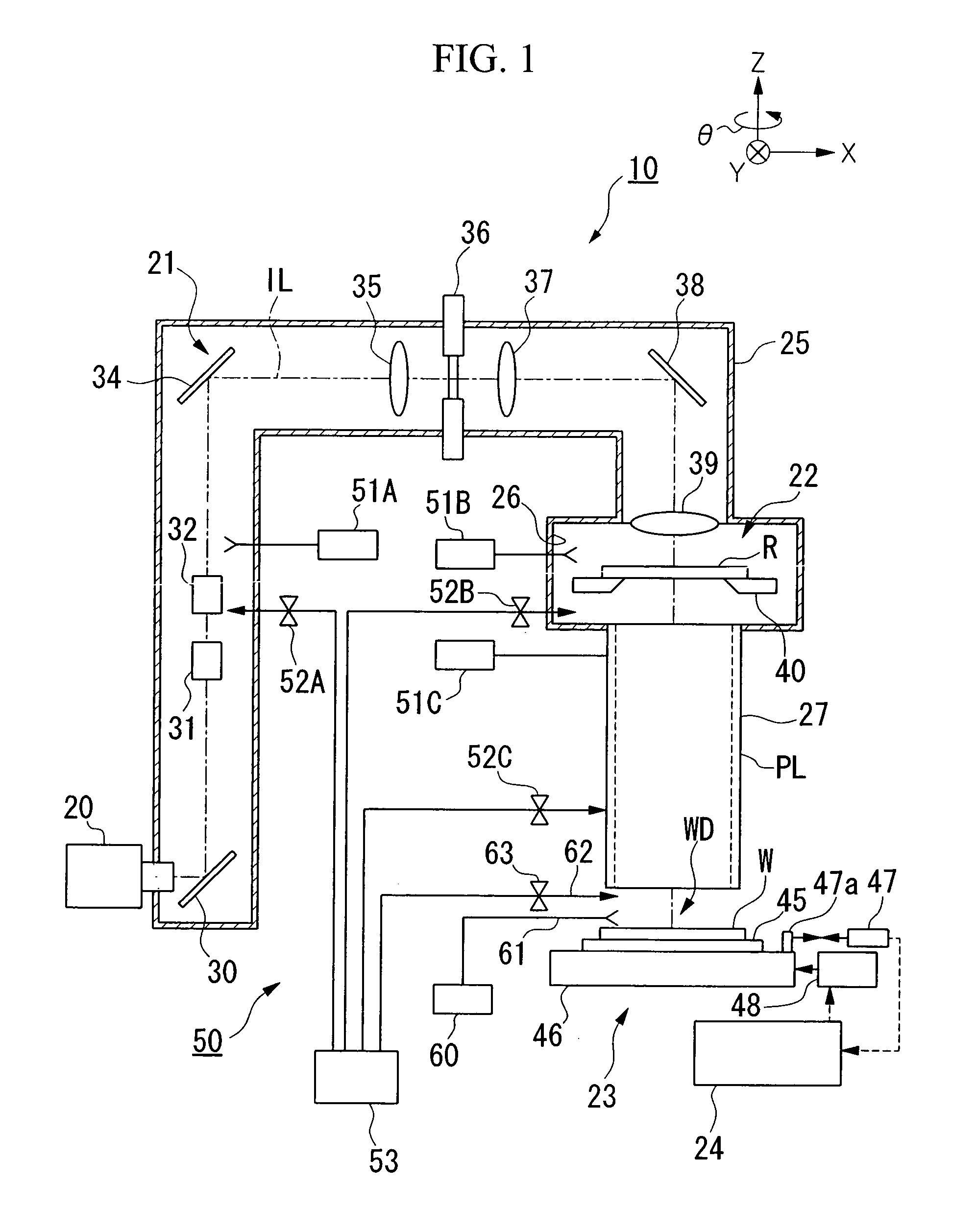
[0098]The exhaust port 110 is annularly provided around the mount position of the wafer W and closer to the wafer W side than the moving mirror 47a of the laser interferometer. In the embodiment, the exhaust port 110 moves together with the wafer W, is provided in the wafer holder 45, and is connected to an unillustrated vacuum pump via the wafer stage 46. The embodiment is not provided with a fixed type exhaust port (the exhaust port 66 shown in FIG. 2) which is located on the projection optical system PL side as illustrated in the first embodiment.

[0099]The exposure appa...


PUM

PropertyMeasurementUnit
wavelengthaaaaaaaaaa
optical path lengthaaaaaaaaaa

Abstract

According to one embodiment of the invention, a pattern of a mask is transferred onto a substrate via a projection optical system using an energy beam by placing a substrate on side of an energy beam emitting end portion of projection optical system, when the substrate is exposed, and placing an object on the side of the energy beam emitting end portion of the projection optical system in place of the substrate when the substrate is exchanged. This can adequately remove a light absorptive substance from the region near an output end of the projection optical system and can maintain the gas state even at a time of moving or replacing the substrate.

Description

[0001]This is a Continuation of Application No. PCT / JP03 / 04515 filed Apr. 9, 2003. The entire disclosure of the prior application is hereby incorporated by reference herein in its entirety.TECHNICAL FIELD[0002]The present invention relates to an exposure method, an exposure apparatus, and a method for manufacturing a device for manufacturing electronic devices, such as semiconductor devices, liquid crystal display devices, image pickup devices (CCD or so) and thin film magnetic heads.BACKGROUND ART[0003]In manufacturing electronic devices, such as semiconductor devices and liquid crystal display devices, in a photolithography process, a projection exposure apparatus is used which projects a pattern image of a mask or reticle (hereinafter called “reticle”) having a pattern formed thereon on each projection (shot) area on a substrate which is coated with a photosensitive agent (resist) via a projection optical system. Circuits of an electronic device are transferred by exposing a circ...

Claims


Application Information

Patent Timeline
Patent Type & Authority Patents(United States)
IPC IPC(8): G03B27/42G03B27/52G03F7/20
CPCG03F7/707G03F7/70733G03F7/70775G03F7/70933G03F7/70866G03F7/70908G03F7/70808G03F7/20
Inventor NAGASAKA, HIROYUKIAOKI, TAKASHI
Owner NIKON CORP
Why Eureka
Try Eureka