Hybrid-powered vehicle

Inactive Publication Date: 2006-09-05
HINO MOTORS LTD
View PDF9 Cites 21 Cited by
  • Summary
  • Abstract
  • Description
  • Claims
  • Application Information

AI Technical Summary

Benefits of technology

[0009]The inventors of the present invention focused to the fact that, even when a slip between an input shaft and an output sh

Problems solved by technology

Moreover, such slip occurs when power is transmitted between the input shaft and the output shaft of t

Method used


Image

  • Hybrid-powered vehicle
  • Hybrid-powered vehicle
  • Hybrid-powered vehicle

Examples


Example

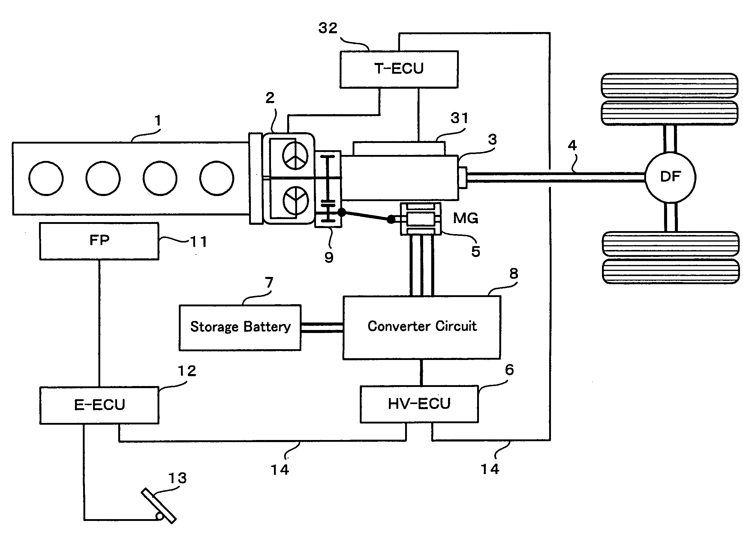
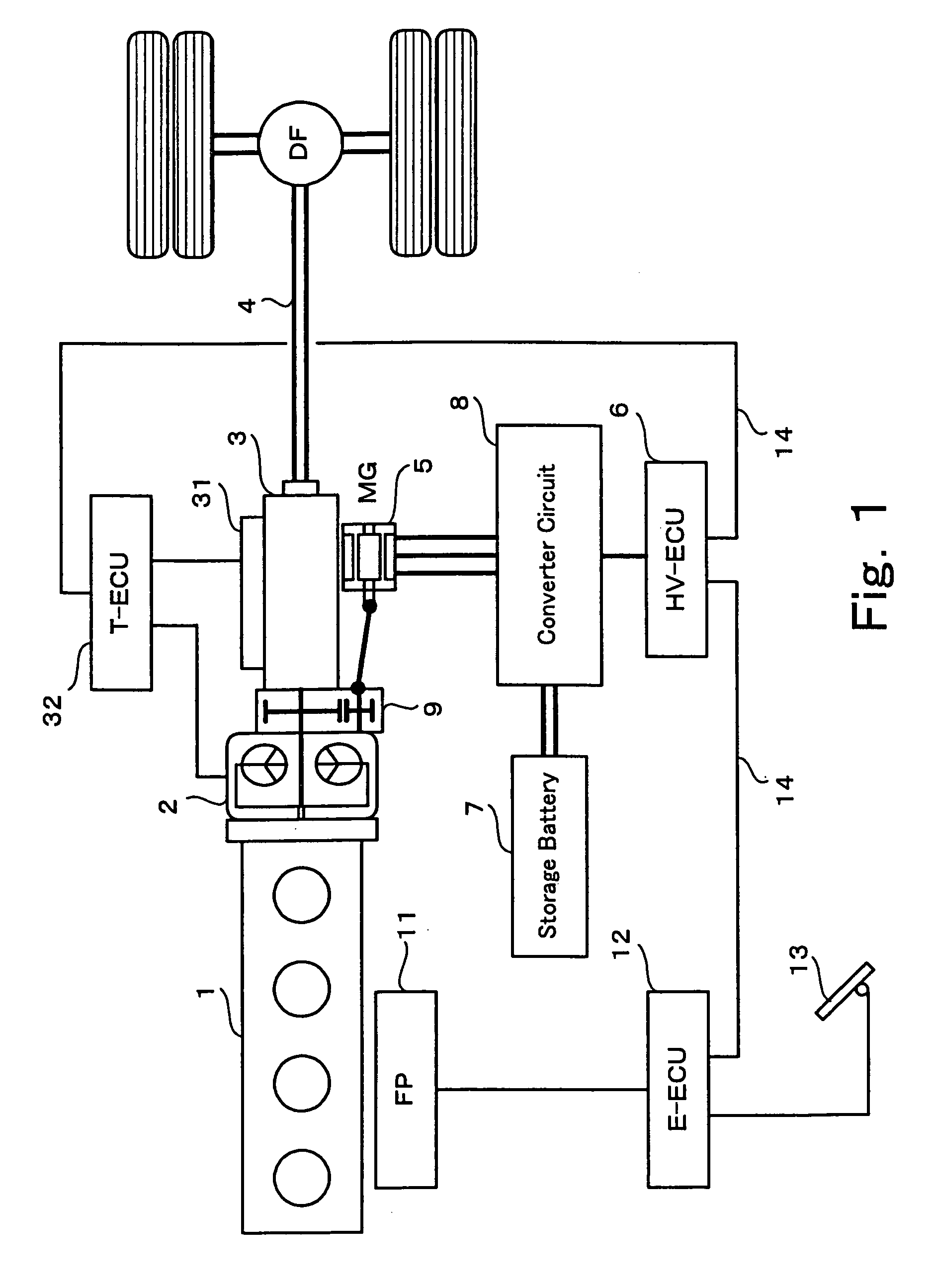
[0022]FIG. 1 is a block diagram showing a construction of an embodiment of a hybrid-powered vehicle according to the present invention. An output shaft of an internal combustion engine 1 is directly connected to an input shaft of a hydraulic torque converter 2. An output shaft of the hydraulic torque converter 2 is fixedly connected to an input shaft of a multistage transmission 3 through a coupling unit 9. The multistage transmission 3 includes an actuator 31 for mechanically controlling a combination of shift gears of the multistage transmission 3 and a transmission control circuit 32 for electrically controlling the actuator 31. The transmission control circuit 32 comprises a program control circuit (ECU).

[0023]The transmission control circuit 32 determines an optimal gear ratio of the multistage transmission according to an input information including vehicle speed, engine rotation, operating information of accelerator pedal, etc. The actuator 31 mechanically controls the transm...


PUM


Abstract

A rotary shaft of a motor-generator of a hybrid-powered vehicle is connected to an output shaft of a torque converter connected to an output shaft of an internal combustion engine. A control of acceleration or deceleration of the vehicle is assisted by controlling the motor-generator as a motor or a generator during a time period in which a slip occurs in the torque converter with a speed change control.

Description

BACKGROUND OF THE INVENTION[0001]1. Field of the Invention[0002]The present invention relates to a hybrid-powered vehicle equipped with an internal combustion engine and a motor-generator. The present invention relates to a technology for realizing a hybrid-powered vehicle by mounting, as a power source, an internal combustion engine and a motor-generator on the vehicle having a power transmission system including a torque converter and a multistage transmission. The present invention relates to an improvement of drivability of a hybrid-powered vehicle and a reduction of energy loss caused by a torque converter of the vehicle.[0003]2. Description of Related Art[0004]In order to effectively utilize torque of an internal combustion engine of a vehicle as a power source thereof in a wide speed range, a transmission is provided between the power source and an axle of the vehicle. Besides, the vehicle having an automatic transmission, which does not require gear shift by a clutch pedal d...

Claims


Application Information

Patent Timeline
IPC IPC(8): B60K1/00B60K6/485B60W20/00B60K6/547B60K17/04B60L50/16B60W10/04B60W10/08B60W10/10B60W10/11F16H59/46F16H61/14
CPCB60K6/48B60K6/547B60W10/08B60W10/10F16H61/14B60L2240/486B60W20/00F16H2061/145B60W2520/105F16H2059/467F16H2061/0433Y02T10/6221F16H2063/506B60W2510/0241Y02T10/62B60W20/15
Inventor YAMAGUCHI, KOICHI
Owner HINO MOTORS LTD
Why Eureka
Try Eureka