Power transmission device and portable power working machine provided with the same

a technology of power transmission device and working machine, which is applied in the direction of machines/engines, manufacturing tools, and manufacturing tools, etc., can solve the problems of not being able to install such a tension roller, taking a lot of time and trouble to loosen the number of bolts employed for fixing the supporting member, and not being able to use the aforementioned tension roller in many cases. , to achieve the effect of constant and appropriate tension, easy, swift and appropriate adjustment of the distance between th

Inactive Publication Date: 2006-09-05
KIORITZ
View PDF12 Cites 27 Cited by
  • Summary
  • Abstract
  • Description
  • Claims
  • Application Information

AI Technical Summary

Benefits of technology

[0009]The present invention takes into account the aforementioned problems. Hence, an object of the present invention is to provide a power transmission device which is relatively simple in structure and is capable of easily, swiftly and appropriately altering the distance between the axes of a pair of transmission wheels such as pulleys, thereby enabling a power transmission member such as an endless belt to be kept under a constant and appropriate amount of tension without necessitating the employment of a tension roller. A further object of the present invention is to provide a portable power working machine that includes such a power transmission device.

Problems solved by technology

However, in the case of portable power working machines where it is strongly desired to miniaturize and lighten the machine as much as possible, it may not be possible to install such a tension roller due to the limited space available in the machine.
Further, since the initially set tension of the belt generally would gradually loosen due to the elongation or wear of the belt, depending on the duration or environments of use, the employment of only the aforementioned tension roller may not be sufficient in many cases.
However, the aforementioned power transmission device where the distance between the axes of a pair of pulleys is made adjustable by way of the screw feeding using a threaded rod is problematic when exchanging the belt or adjusting the distance between the axes (the adjustment of the tension of the belt).
Specifically, it takes a lot of time and trouble to loosen the number of bolts employed for fixing the supporting member as well as to suitably clamp or loosen the aforementioned threaded rod, etc.
Due to the limited rotating angle of these tools as mentioned above, these tools must be usually removed from the threaded rod before finishing the needed rotation of the threaded rod, thus requiring time-consuming manipulations of tools when exchanging the belt as well as taking a lot of time and trouble in the adjustment of the distance between the pair of axes as mentioned above.
Additionally, since the belt is mounted under a great amount of tension, a very large force is needed to rotate the threaded rod when making the aforementioned adjustment of the distance between the axes.
At the same time, because the determination as to whether the degree of tension of the belt is appropriate is based largely on the operator's perception, the tension of the belt is liable to be either insufficient or excessive, thus making the operation of adjusting the distance between a pair of the axes difficult or troublesome.

Method used


Image

  • Power transmission device and portable power working machine provided with the same
  • Power transmission device and portable power working machine provided with the same
  • Power transmission device and portable power working machine provided with the same

Examples


Embodiment Construction

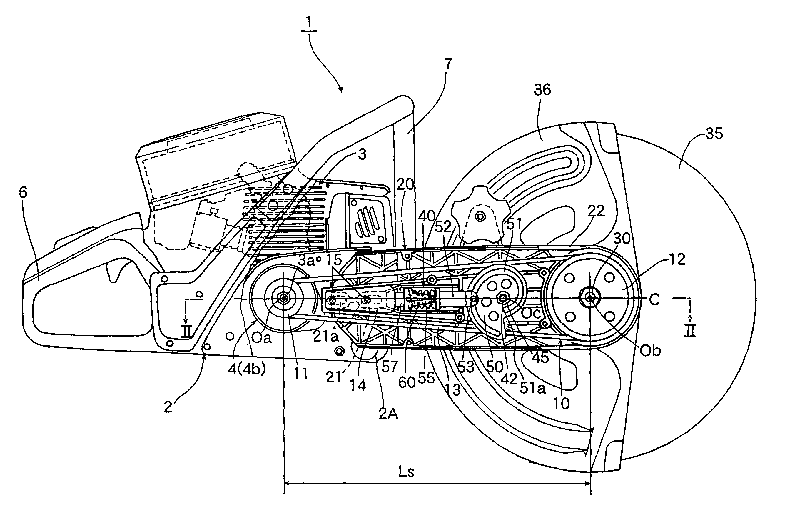
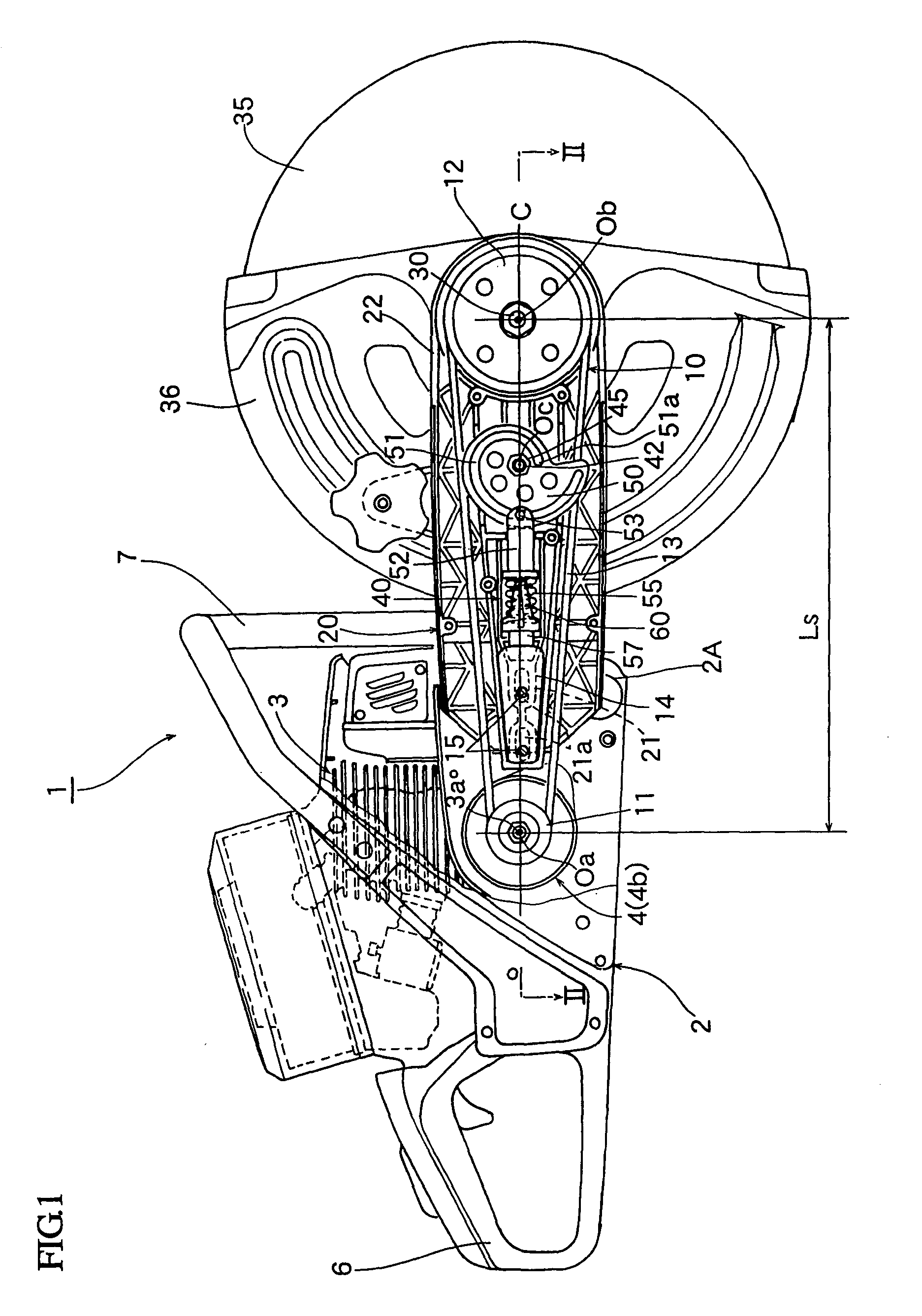
[0027]FIG. 1 shows an entire structure of the concrete cutter 1 excluding a right side body cover 8 (see FIG. 2) and a supporting arm cover 9 (see FIG. 2) both of which are removed for the convenience of explanation. This concrete cutter 1 is provided with a small air-cooled internal combustion engine 3 functioning as a prime mover and mounted inside the main housing 2 which is provided with a rear handle 6 and a front handle 7. Herein, this main housing 2 serves also as a driving side supporting member of the power transmission device 10 according to this embodiment. A boss 4a for mounting a centrifugal shoe of a centrifugal clutch 4 is externally and fixedly fitted on a crankshaft 3a of the engine 3 by a nut 4c. To a clutch drum 4b of this centrifugal clutch 4 is integrally attached a first pulley (multiple thread V pulley) 11 which constitutes part of the power transmission device 10.

[0028]A distal end portion 21 of a supporting arm (a driven side supporting member) 20 having a g...


PUM

PropertyMeasurementUnit
thicknessaaaaaaaaaa
distanceaaaaaaaaaa
angleaaaaaaaaaa

Abstract

A power transmission device is disclosed which is capable of easily, swiftly and appropriately altering the distance between the axes of a pair of transmission wheels such as pulleys, enabling an endless belt to be kept under constant and appropriate tension without necessitating a tension roller. This power transmission device comprises an endless belt wound around a pair of transmission wheels; and a cam-type adjusting mechanism which is interposed between a driving side supporting member and a driven side supporting member and configured to adjust a distance between the axes of the wheels. This cam-type adjusting mechanism comprises a supporting shaft secured to either the driving side supporting member or the driven side supporting member and disposed parallel to the rotational axes of the wheels; and a cam rotatably secured via a manipulating boss member to the supporting shaft.

Description

BACKGROUND OF THE INVENTION[0001]1. Field of the Invention[0002]The present invention relates to a power transmission device, and to a portable power working machine such as a concrete cutter, which is provided with such a power transmission device. In particular, the present invention relates to a power transmission device configured to perform the power transmission by means of a power transmission member such as an endless belt or an endless chain wound around a pair of transmission wheels such as pulleys or sprocket wheels to thereby interconnect the transmission wheels. The present invention also relates to a portable power working machine such as a concrete cutter, which is provided with the above-mentioned power transmission device.[0003]2. Description of the Related Art[0004]In the case of a portable power working machine such as a concrete cutter, a winding transmission type power working machine has been widely employed as a power transmission device for transmitting the p...

Claims


Application Information

Patent Timeline
Patent Type & Authority Patents(United States)
IPC IPC(8): F16H7/14F02B63/00B23D47/12F16H7/08
CPCB23D47/12F16H7/14F16H2007/0806
Inventor TAOMO, TOSHIOKOBAYASHI, FUJIO
Owner KIORITZ
Why Eureka
Try Eureka