Dynamic response ankle-foot orthosis with joint

Inactive Publication Date: 2006-09-05
DAVIS LOCKE
View PDF3 Cites 9 Cited by
  • Summary
  • Abstract
  • Description
  • Claims
  • Application Information

AI Technical Summary

Benefits of technology

[0010]Through a dynamic orthosis, a more normal gait pattern can be obtained with less compensatory activity required by proximal segments of the body. The present invention, with its pliable dynamically responding ankle-foot orthosis, provides predetermined corrective forces on the foot and ankle complex during different events of the gait cycle. By combining a dynamically responsive orthosis with a pivot location, such as a mechanical joint, the orthosis, which began as a tre

Problems solved by technology

This type of scenario is common in athletes who have good mobility and control of the ankle foot co

Method used


Image

  • Dynamic response ankle-foot orthosis with joint
  • Dynamic response ankle-foot orthosis with joint
  • Dynamic response ankle-foot orthosis with joint

Examples


Example

DETAILED DESCRIPTION OF THE DRAWINGS

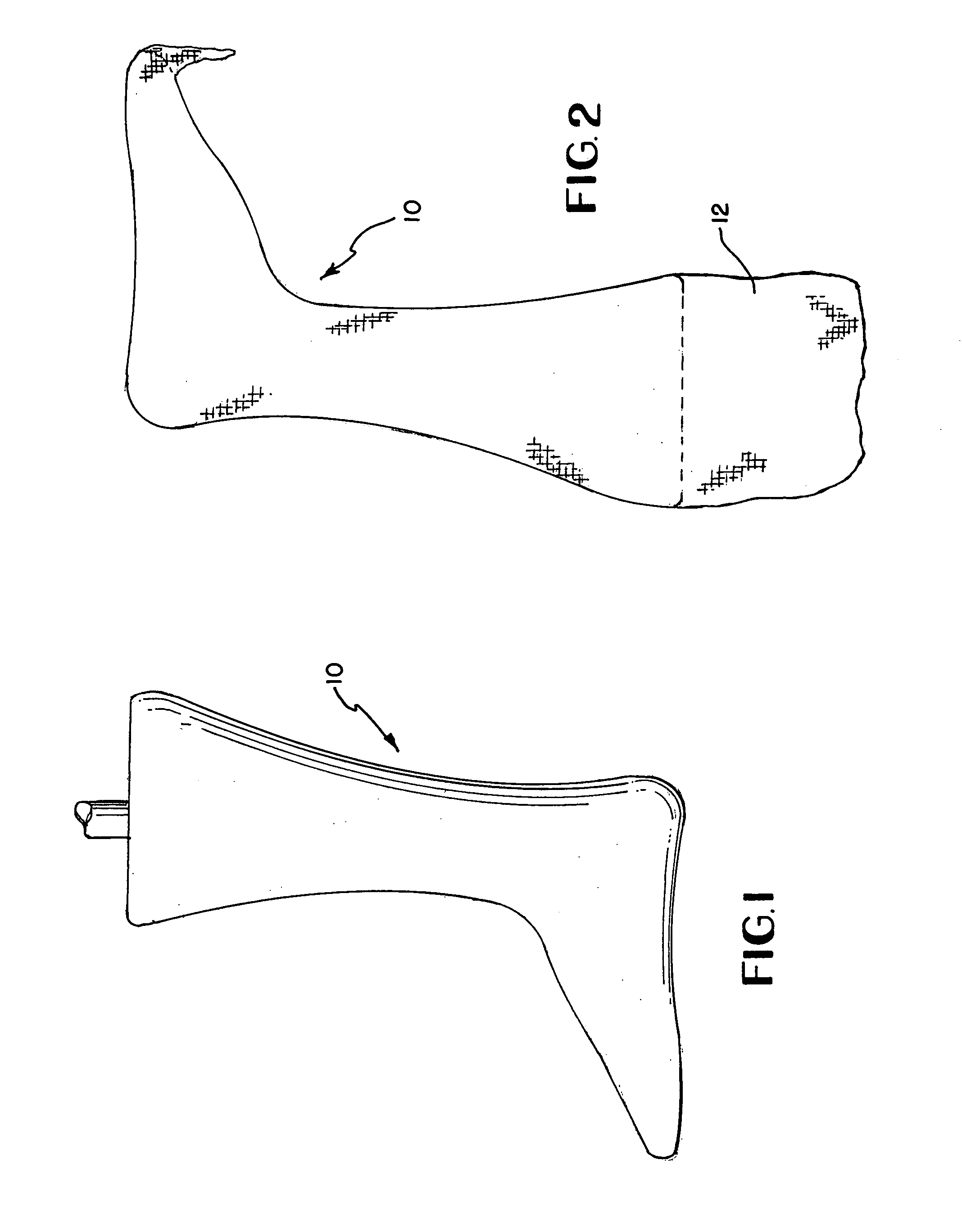
[0021]Referring now to FIG. 1, a positive mold 10 of the foot of a patient is illustrated. U.S. Pat. No. 6,334,854 incorporated herein by reference describes one method of making mold 10. A cast is typically taken of a patient's leg and foot. The cast is then sealed and poured with molding plaster. After the molding plaster has hardened, the outer cast is removed and the technician is left with a positive mold of the patient's lower limb. This positive mold 10 may then be modified and smoothed according to specifications desired by the clinician. Additionally, molds 10 can be created according to the measurements taken from the limb of a patient to create mold 10.

[0022]After obtaining a suitable mold 10, the mold is sealed with a sealing and release agent that will seal the mold and not bond to the elastomeric resin. FIG. 2 shows a fabric 12 placed over the mold 10. The fabric 12 may be a nylon stockinette or other appropriate material such as one...


PUM


Abstract

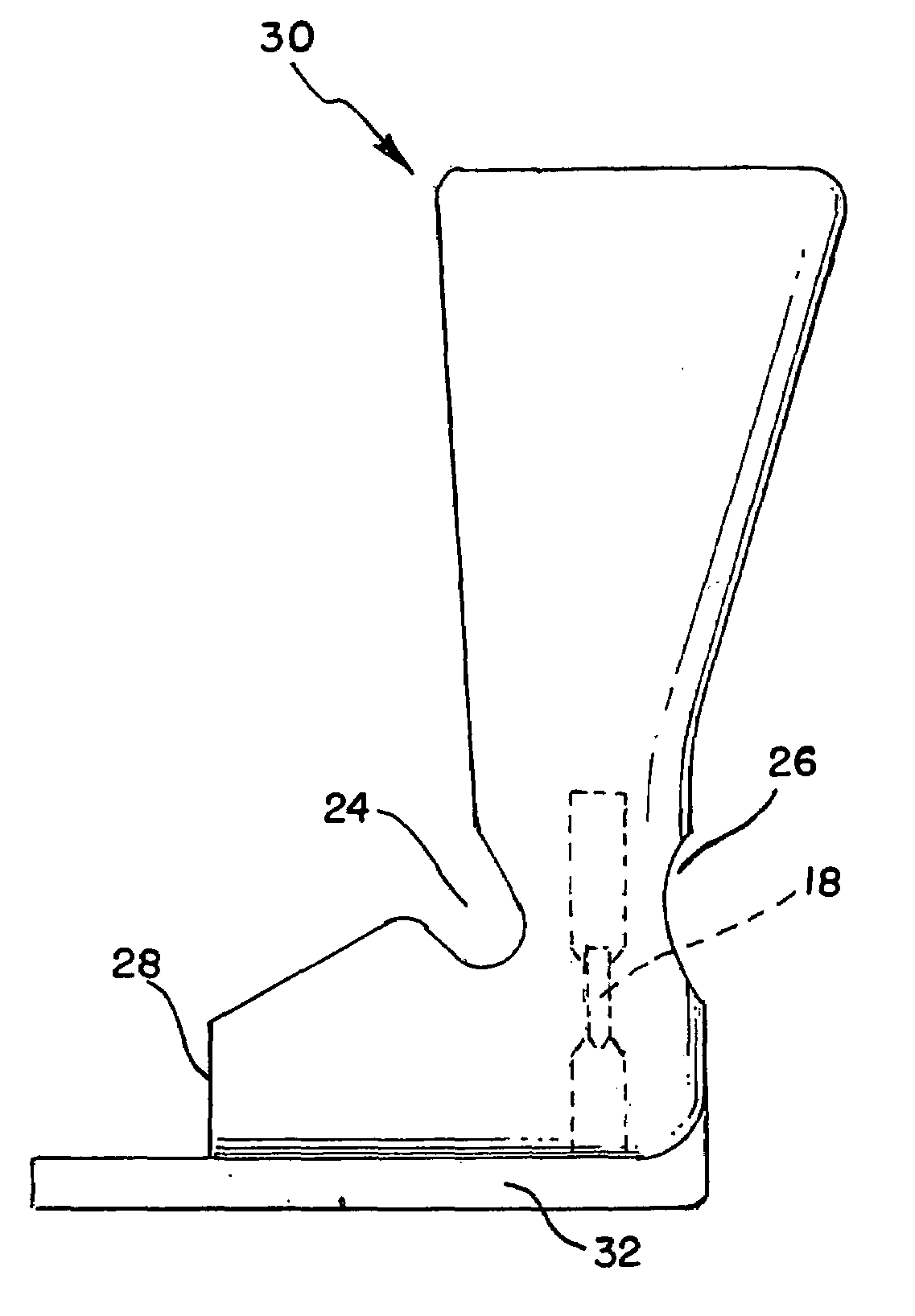
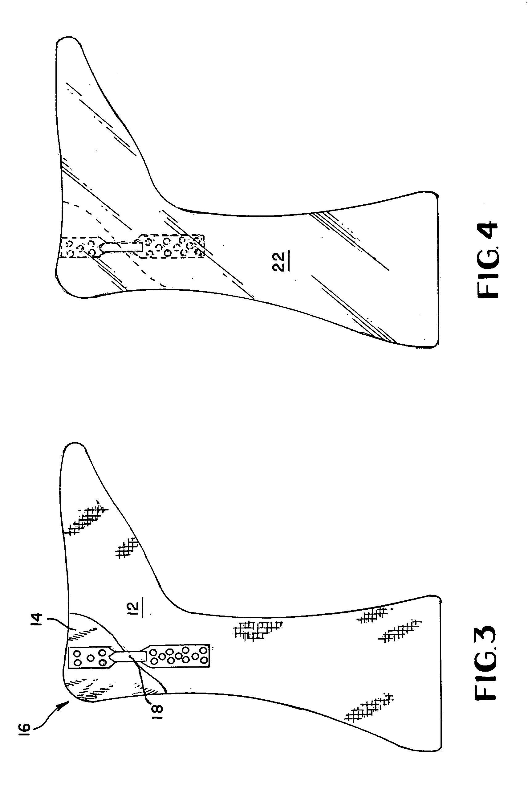
An orthotic device is developed and customized to control the (un)desired movements of the patient's defective lower limb. The device incorporates a footplate made of a rubber like elastomeric material, a proximal segment that encompasses the foot at the metatarsal phalengeal joints and the dorsal aspect of the foot, and a second proximal segment that encompasses the shin portion of the leg. Motion of the patient's talocrual is allowed and controlled by laminating mechanical joints to the medial and lateral aspects of the brace and providing cutouts in the lamination just anterior and posterior to the ankle joint axis of motion.

Description

CLAIM OF PRIORITY[0001]This application is a continuation-in-part filed Jun. 11, 2001 of U.S. patent application Ser. No. 09 / 878,621 now U.S. Pat. No. 6,726,645, which is a divisional application filed Sep. 27, 1999 of U.S. patent application Ser. No. 09 / 405,074 now U.S. Pat. No. 6,334,854.BACKGROUND OF THE INVENTION[0002]1. Field of the Invention[0003]This application relates to orthoses, and more particularly to ankle-foot orthotic braces which have a joint for allowing movement along a rotational axis.[0004]2. Detailed Description of Related Art[0005]Ankle foot orthoses are commonly used as foot, ankle, and leg braces for improving movement. Years ago a leg brace would consist of two metal bars and a stirrup attached to the sole of the shoe. A horizontally positioned padded, metal band, contoured to the back of the leg calf, would connect the two metal bars. A broad strap across the anterior section of the calf would hold the brace in place. This type of brace has limited use tod...

Claims


Application Information

Patent Timeline
IPC IPC(8): A61F5/00
CPCA61F5/0111
Inventor DAVIS, LOCKE
Owner DAVIS LOCKE
Why Eureka
Try Eureka