Fluid application device

Inactive Publication Date: 2006-09-05
JAPAN TOBACCO INC
View PDF19 Cites 6 Cited by
  • Summary
  • Abstract
  • Description
  • Claims
  • Application Information

AI Technical Summary

Benefits of technology

[0023]The aforementioned application nozzle has a polished surface on an inner wall of a passage communicated with the discharge hole, thereby reducing flow resistance of the fluid in the application nozzle. If the polished surfac

Problems solved by technology

For example, even if the fluid level in the second tank is constant, there is a possibility that the supply pressure of the fluid at an inlet of

Method used


Image

  • Fluid application device
  • Fluid application device
  • Fluid application device

Examples


Example

BEST MODE OF CARRYING OUT THE INVENTION

[0029]Hereinafter, a specific embodiment of the present invention for a cigarette manufacturing machine will be explained.

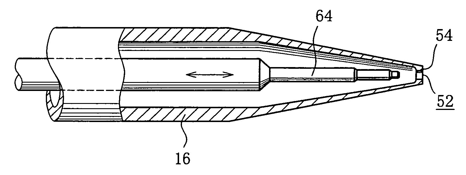
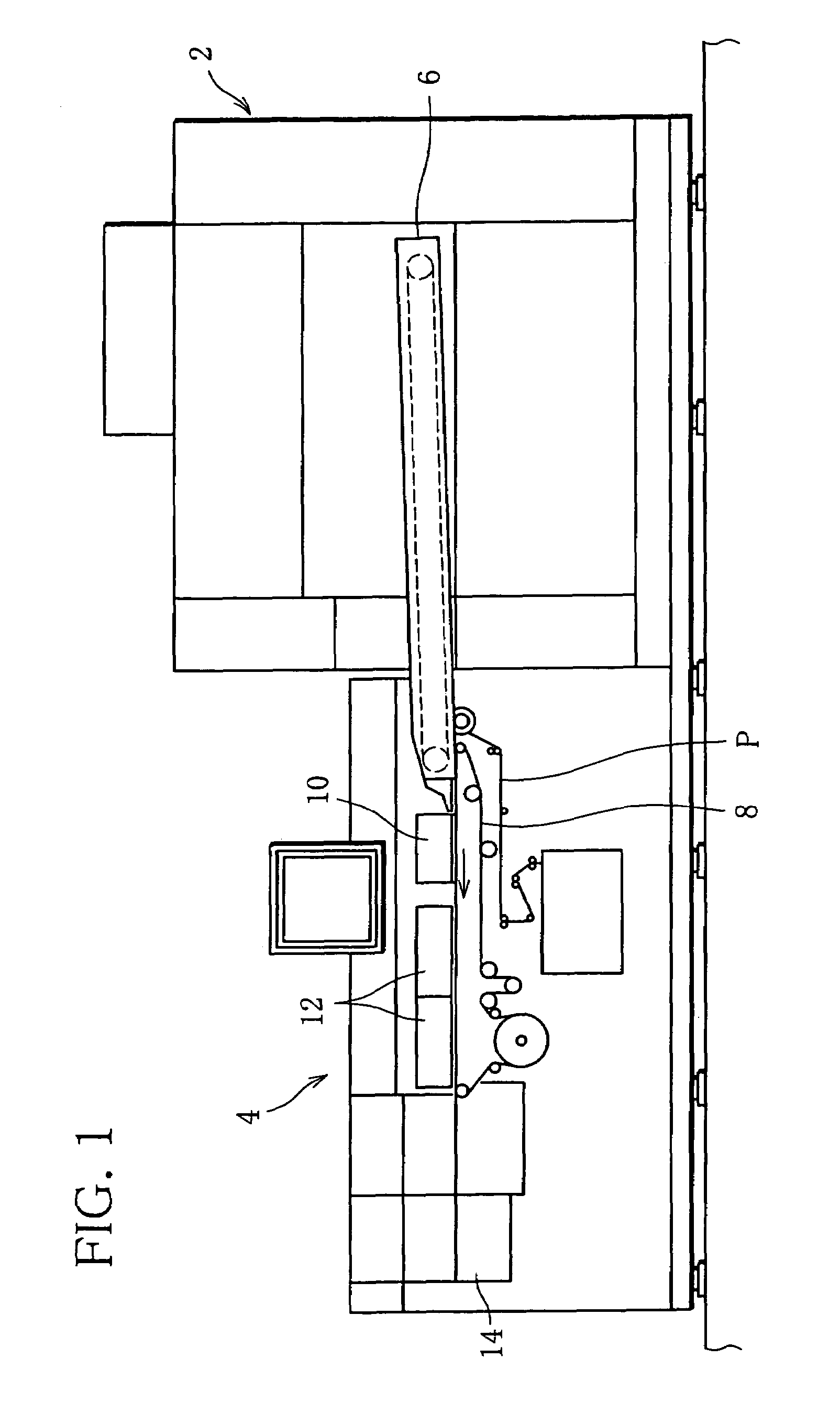
[0030]As illustrated in FIG. 1, the cigarette manufacturing machine comprises a feeding device 2 and a rod-forming device 4. As publicly known, the feeding device 2 has a suction conveyer 6. By the suction conveyer 6, shredded tobacco is formed in a layer and supplied to the rod-forming device 4. The rod-forming device 4 causes a cigarette wrapping paper P, together with endless garniture tape 8, to travel and receives the shredded tobacco layer thereon. That is, the shredded tobacco layer is transferred from a terminal end of the suction conveyer 6 on the wrapping paper P. Then, the shredded tobacco layer travels with the wrapping paper P and is compression-molded into a cylindrical rod with molds (tongue). The wrapping paper P is first bent into the shape of a U around the shredded tobacco layer in the process of travellin...


PUM


Abstract

A fluid application device stores seam paste in a reservoir tank 18 and feeds the seam paste to a pressure tank 20 through a feed pump 22. Inside of the pressure tank 20 is maintained under a given air pressure by a pneumatic unit 26, and the seam paste is supplied from the pressure tank 20 to an application nozzle 16 through a supply pipe 24. A level sensor 28 detects fluid level of stored seam paste in the pressure tank 20, and a detection signal is input to a controller 30. The controller 30 controls operation of the feed pump 22 based on the detection signal that is transmitted from the level sensor 28 and also controls a supply amount of the seam paste to the pressure tank 20 to maintain the fluid level in the pressure tank 20 at a fixed level.

Description

[0001]This application is a Continuation of copending PCT International Application No. PCT / JP02 / 05707 filed on Jun. 7, 2002, which designated the United States, and on which priority is claimed under 35 U.S.C. § 120, and this Nonprovisional application claims priority under 35 U.S.C. § 119(a) on Patent Application No(s). 2001-174152 and 2001-297089 filed in Japan on Jun. 8, 2001 and Sep. 27, 2001, respectively, the entire contents of which are hereby incorporated by reference.TECHNICAL FIELD[0002]The present invention relates to a fluid application device discharging fluid from a tip end of a nozzle and continuously applying the fluid to an object that relatively travels with respect to the application device.BACKGROUND ART[0003]An application device of this kind is used, for example, for continuously applying seam paste to one of side edge portions of wrapping paper when the wrapping paper travels through a rod-forming section of a cigarette manufacturing machine, the side edge po...

Claims


Application Information

Patent Timeline
IPC IPC(8): B05B1/02B05C11/00A24C5/24B05C5/02B05C11/10
CPCA24C5/24B05C11/10B05C5/0225B05C11/101B05C11/1013B05C11/1047
Inventor KUSHIHASHI, SHIGENOBUHORIKAWA, SYOZOUENO, JUNJI
Owner JAPAN TOBACCO INC
Why Eureka
Try Eureka