Slurry treatment and shipping method
- Summary
- Abstract
- Description
- Claims
- Application Information
AI Technical Summary
Benefits of technology
Problems solved by technology
Method used
Image
Examples
Embodiment Construction
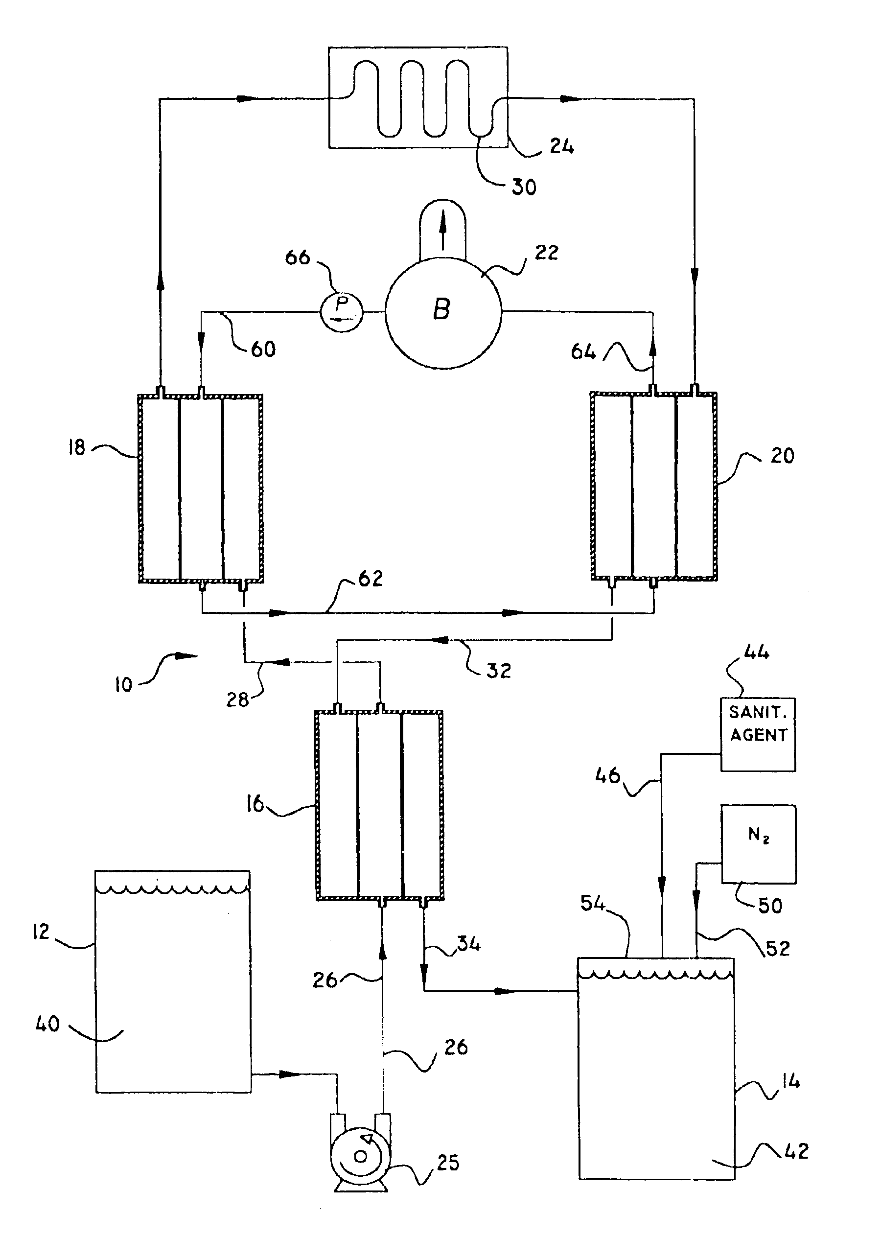
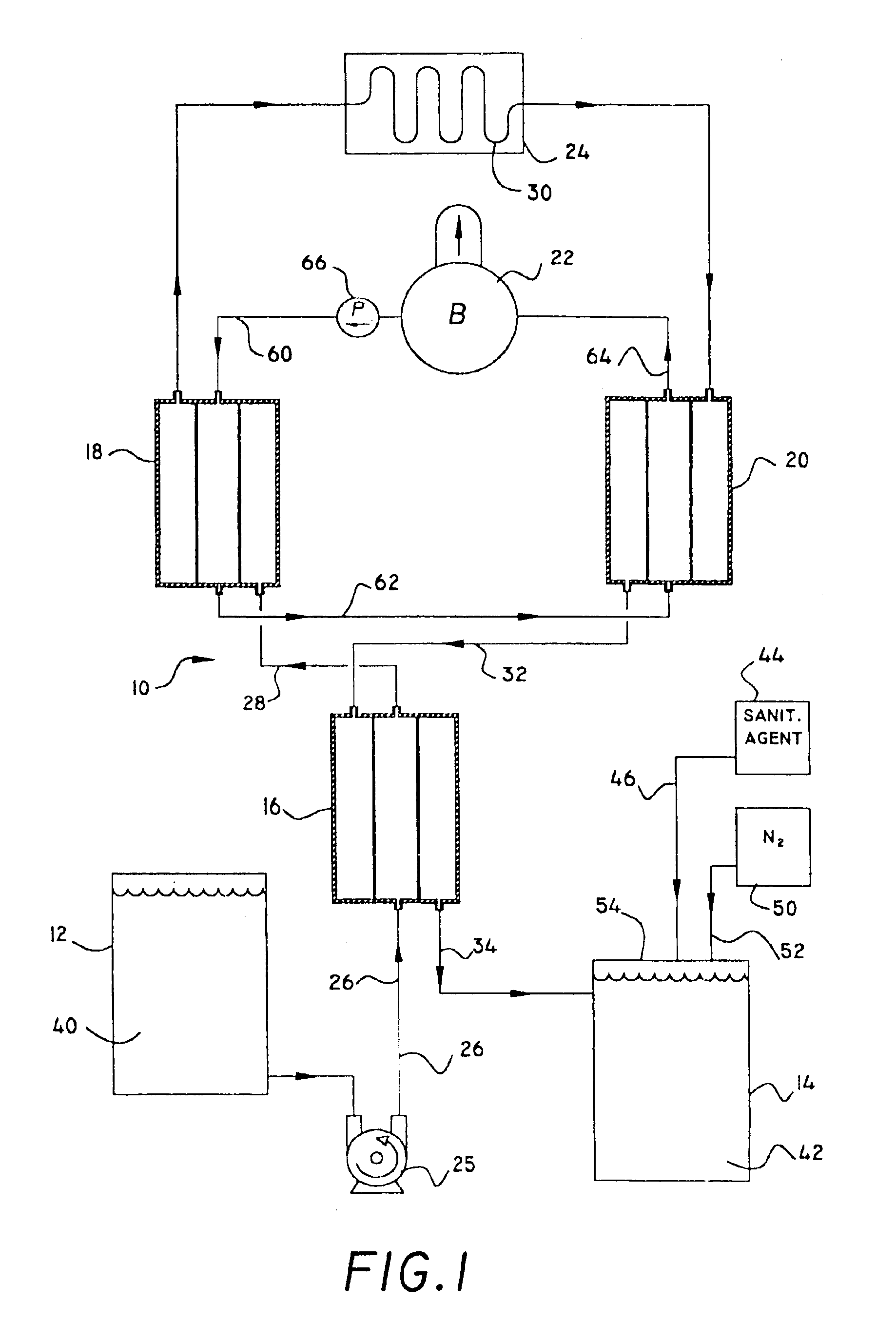
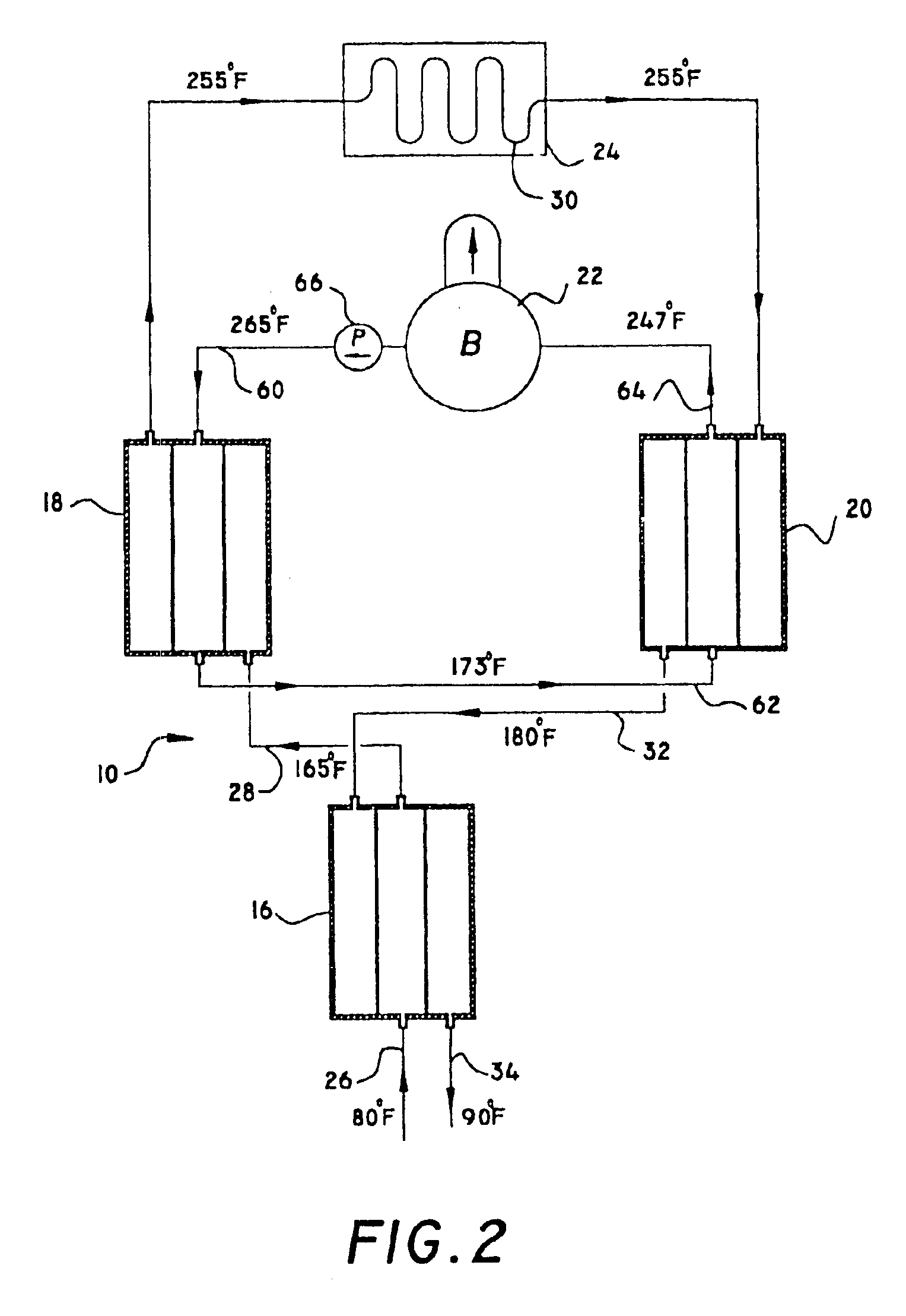
[0018]FIGS. 1 and 2 of the drawings schematically depict the major components of a system 10 for continuously sterilizing contaminatable slurry, according to a preferred embodiment of this invention. These comprise a supply tank 12, a storage tank 14, serially arranged heat exchangers 16, 18 and 20, a hot water boiler 22, and a manifold 24.
[0019]A pump 25 at supply tank 12 pumps slurry through a piping system which includes a supply pipe 26 from pump 25 to heat exchanger 16, a connecting pipe 28, that connects heat exchangers 16 and 18, slurry manifold piping 30, that connects heat exchangers 18 and 20, a connecting pipe 32, that connects heat exchangers 20 and 22, and an outlet pipe 34, that exits heat exchanger 16 and enters storage tank 14. The direction of slurry flow is indicated by arrows in FIGS. 1 and 2. Pipe 34 can, alternatively, connect directly into the intake of a further industrial process, such as paper making. Tanks 12 and 14 may be stationary, or mobile, such as mou...
PUM
| Property | Measurement | Unit |
|---|---|---|
| Temperature | aaaaa | aaaaa |
| Temperature | aaaaa | aaaaa |
| Temperature | aaaaa | aaaaa |
Abstract
Description
Claims
Application Information
 - R&D
- Intellectual Property
- Life Sciences
- Materials
- Tech Scout
- Unparalleled Data Quality
- Higher Quality Content
- 60% Fewer Hallucinations
Browse by: Latest US Patents, China's latest patents, Technical Efficacy Thesaurus, Application Domain, Technology Topic, Popular Technical Reports.
© 2025 PatSnap. All rights reserved.Legal|Privacy policy|Modern Slavery Act Transparency Statement|Sitemap|About US| Contact US: help@patsnap.com


