
Method and device for removing harmonics in semiconductor plasma processing systems

a plasma processing system and semiconductor technology, applied in the direction of coatings, electric discharge lamps, electric lighting sources, etc., can solve the problems of adversely affecting process uniformity, high excitation frequency, and difficult to maintain high etching,

Inactive Publication Date: 2006-09-05
TOKYO ELECTRON LTD
View PDF12 Cites 25 Cited by
  • Summary
  • Abstract
  • Description
  • Claims
  • Application Information

AI Technical Summary

Benefits of technology

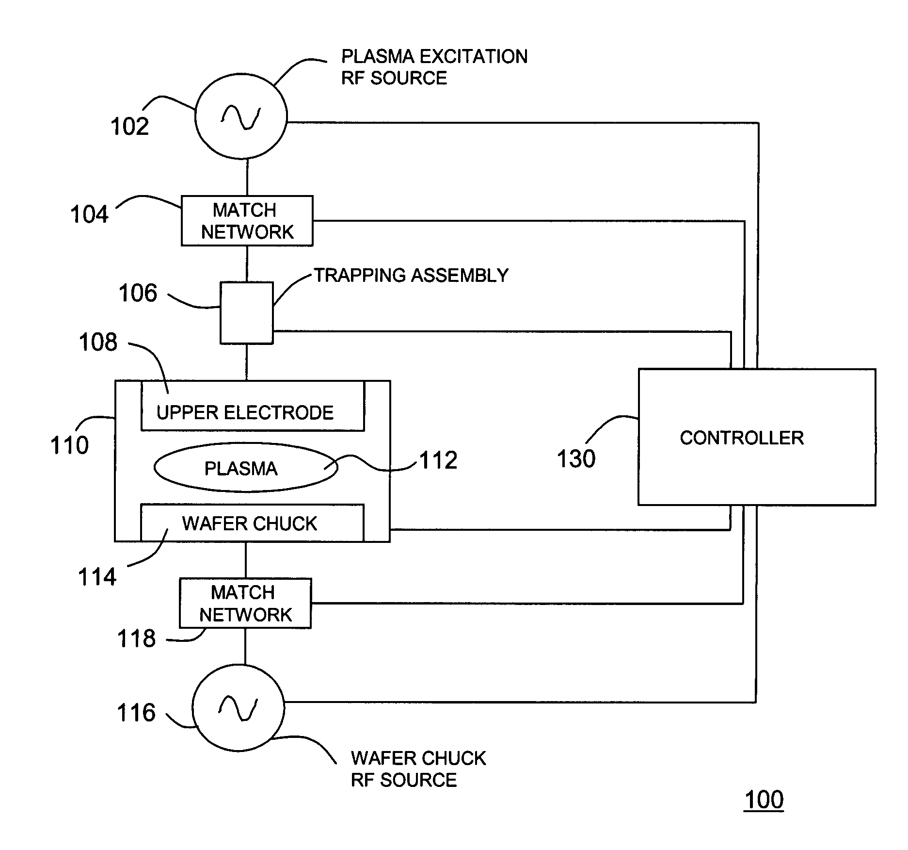
The present invention relates to a plasma processing system that controls the power levels of harmonics of the RF excitation power in plasma processing systems. The system includes a chamber enclosing a plasma region, a source of RF power, and means for transmitting the RF power into the plasma region to create an RF electromagnetic field that interacts with a gas in the plasma region to create a plasma. The system also includes energy controlling members that include RF absorbing loads that have a frequency dependent attenuation characteristic such that the RF absorbing loads remove electrical energy appearing in the plasma at frequencies higher than the fundamental frequency more strongly than energy at the fundamental frequency. The technical effect of the invention is to control the power levels of harmonics of the RF excitation power in plasma processing systems, which can improve the efficiency and stability of plasma processing.

Problems solved by technology

However, maintaining high etching and deposition rate uniformity levels at these very high excitation frequencies and with strong harmonics present has proven to be a difficult feat, for a number of reasons.
Thus, RF electromagnetic field spatial variations are more pronounced at these higher frequencies and this adversely affects process uniformity.
Therefore, harmonics, even if present at very low power levels, can significantly affect process uniformity due to their very unfavorable wavelength-to-wafer-diameter ratio.

Method used


Image

  • Method and device for removing harmonics in semiconductor plasma processing systems
  • Method and device for removing harmonics in semiconductor plasma processing systems
  • Method and device for removing harmonics in semiconductor plasma processing systems

Examples


Embodiment Construction

[0021]A plasma processing system of the type to which this invention is applied includes a chamber which encloses a plasma region filled with an ionizable gas and into which RF electromagnetic energy is coupled. The energy interacts with the gas to initiate and sustain a plasma. According to the invention, one or more components are provided to control the energy contained in harmonics of the fundamental frequency of the RF energy coupled into and out of the plasma. This harmonic attenuation can take place wherever a suitable impedance-matched coupling structure is present, or can be provided to couple the harmonic power out of the plasma.

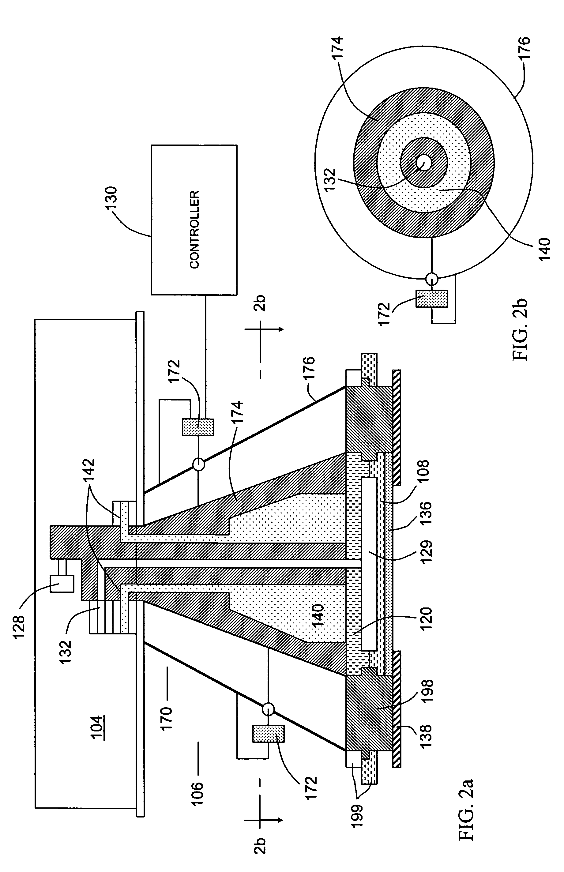
[0022]In one embodiment, frequency selective trap elements are provided, that selectively absorb power associated with certain harmonics while not affecting the others. Desirably, resistive loads are coupled to the transmission line, which delivers the RF electromagnetic energy to the plasma. All harmonics are generated at impedances different from...


PUM

PropertyMeasurementUnit
diameteraaaaaaaaaa
frequencyaaaaaaaaaa
frequenciesaaaaaaaaaa

Abstract

A system and method for maintaining a plasma in a plasma region by supplying RF power at a fundamental frequency to the plasma region together with a gas in order to create an RF electromagnetic field which interacts with the gas to create a plasma that contains electromagnetic energy components at frequencies that are harmonics of the fundamental frequency. The components at frequencies that are harmonics of the fundamental frequency are reduced by placing RF energy absorbing resistive loads in energy receiving communication with the plasma, the resistive loads having a frequency dependent attenuation characteristic such that the resistive loads attenuate electrical energy at frequencies higher than the fundamental frequency more strongly than energy at the fundamental frequency.

Description

CROSS-REFERENCE TO RELATED APPLICATIONS[0001]This is a continuation of International Application No. PCT / US02 / 37326, filed on Nov. 21, 2002, which, in turn, relies upon and claims benefit of the filing date of U.S. Provisional Patent Application No. 60 / 337,171, filed Dec. 10, 2001, the contents of both which are incorporated herein by reference in their entireties.[0002]The present application is related to co-pending applications entitled “Device and Method For Coupling Two Circuit Components Which Have Different Impedances”, PCT Application US01 / 40073, filed Feb. 9, 2001, now U.S. Pat. No. 6,700,458, and “Method and Device for Attenuating Harmonics in Semiconductor Plasma Processing Systems”, PCT Application US01 / 04135, filed Feb. 9, 2001, now U.S. Patent Publication No. US-2003-0057844. Each of these applications is herein incorporated by reference in its entirety.BACKGROUND OF THE INVENTION[0003]In the past, various techniques have been proposed for selective attenuation of harm...

Claims


Application Information

Patent Timeline
Patent Type & Authority Patents(United States)
IPC IPC(8): H01J7/24H01J37/32
CPCH01J37/32183H01J37/32082
Inventor PARSONS, RICHARDJOHNSON, WAYNE L
Owner TOKYO ELECTRON LTD
Learn More