Control method for peak power delivery with limited DC-bus voltage

a control method and dc-bus voltage technology, applied in the control of dynamo-electric converters, motor/generator/converter stoppers, electronic commutators, etc., can solve the problems of affecting the drive performance, increasing the price, and accumulating charges at the midpoint between the two dc linking capacitors

Inactive Publication Date: 2006-09-05
THE BOEING CO
View PDF11 Cites 12 Cited by
  • Summary
  • Abstract
  • Description
  • Claims
  • Application Information

AI Technical Summary

Problems solved by technology

Such inverters require complex control circuitry, each of the redundant switches add to the price of the voltage source inverter, and the charge at the mid point between the two DC linking capacitors can accumulate when switching is not balanced.
As a result, drive performance degrades considerably.
Though fundamental component voltage gain and current waveform characteristics in the overmodulation region are well improved, these schemes are suitable only for an open loop (...

Method used


Image

  • Control method for peak power delivery with limited DC-bus voltage
  • Control method for peak power delivery with limited DC-bus voltage
  • Control method for peak power delivery with limited DC-bus voltage

Examples


Embodiment Construction

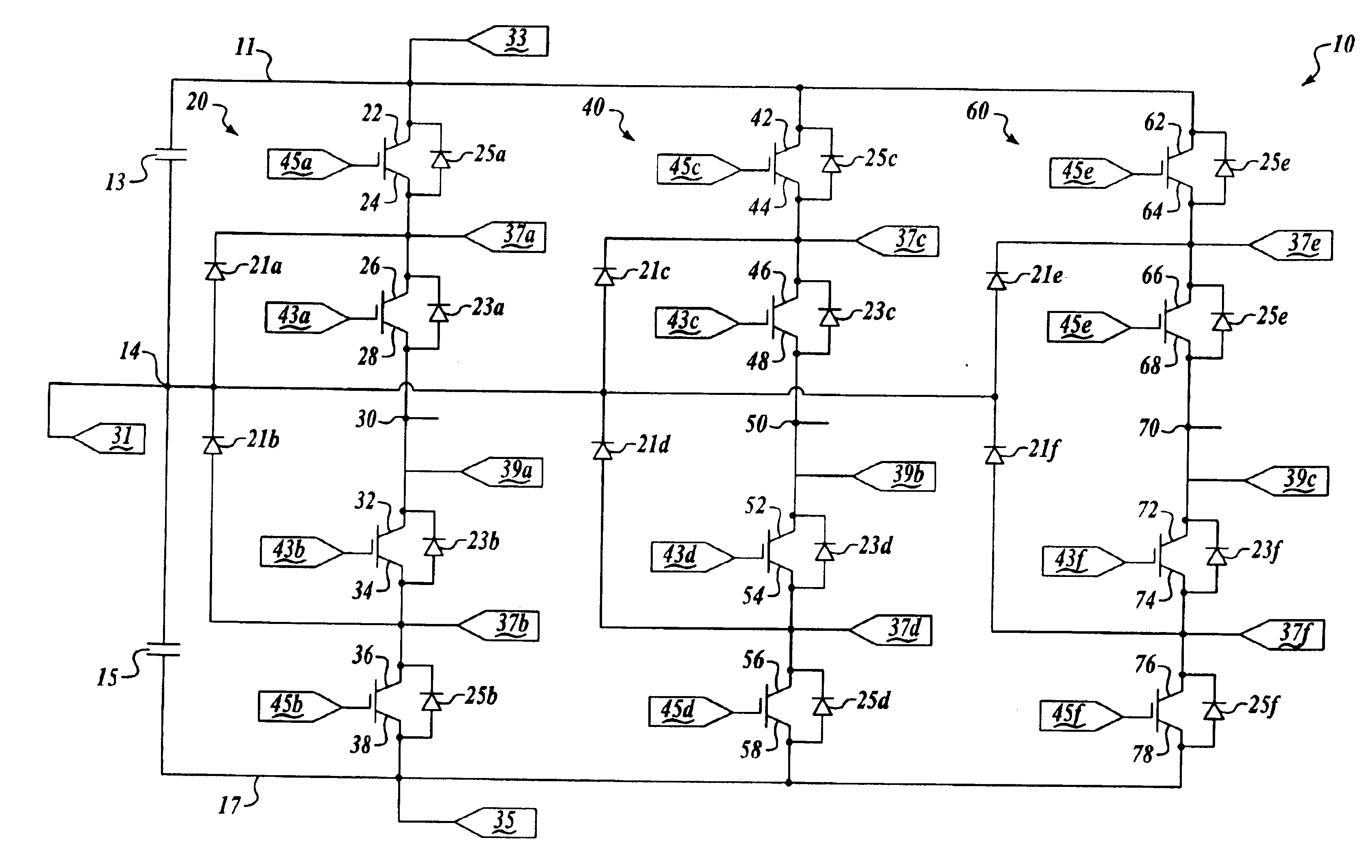
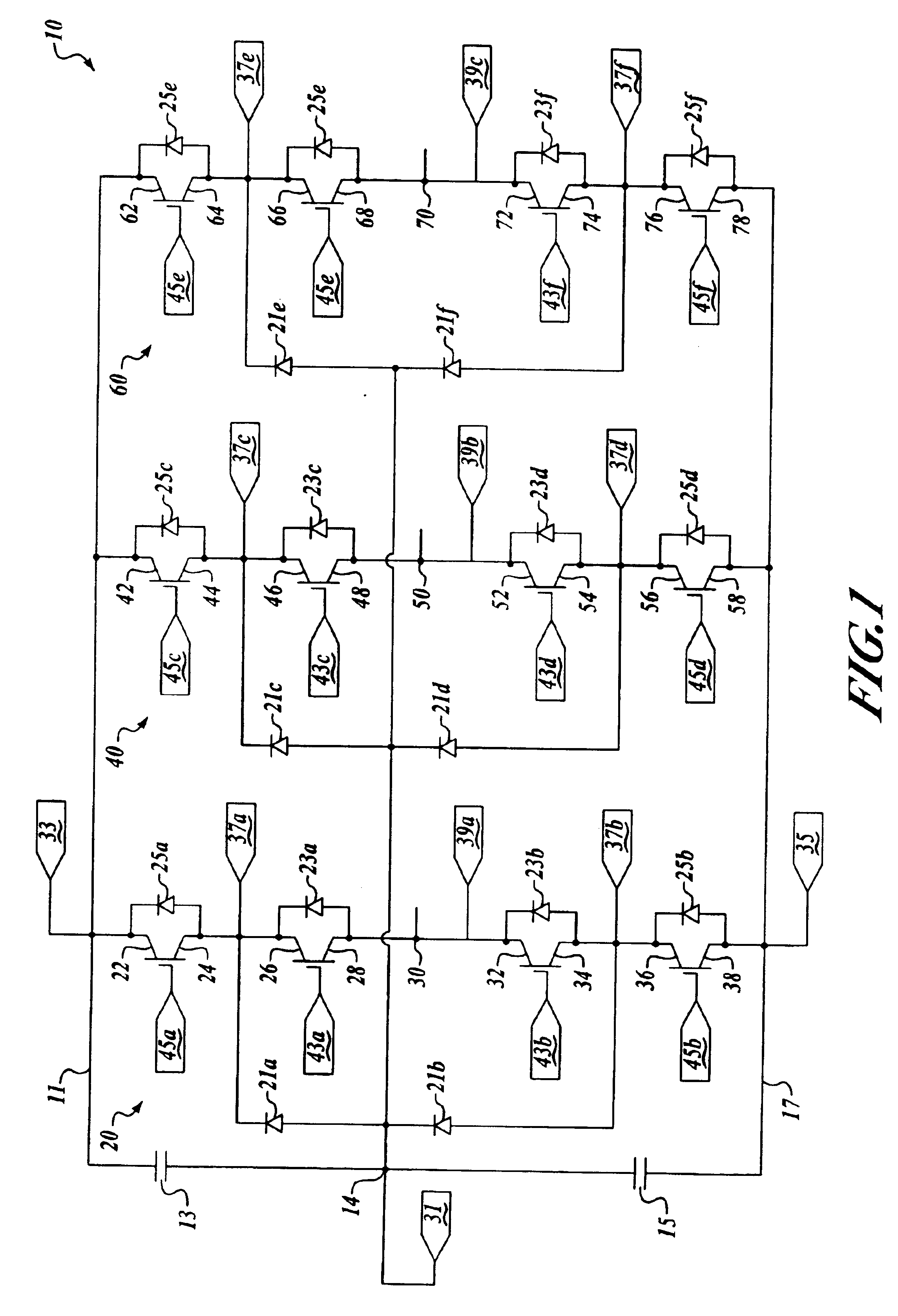
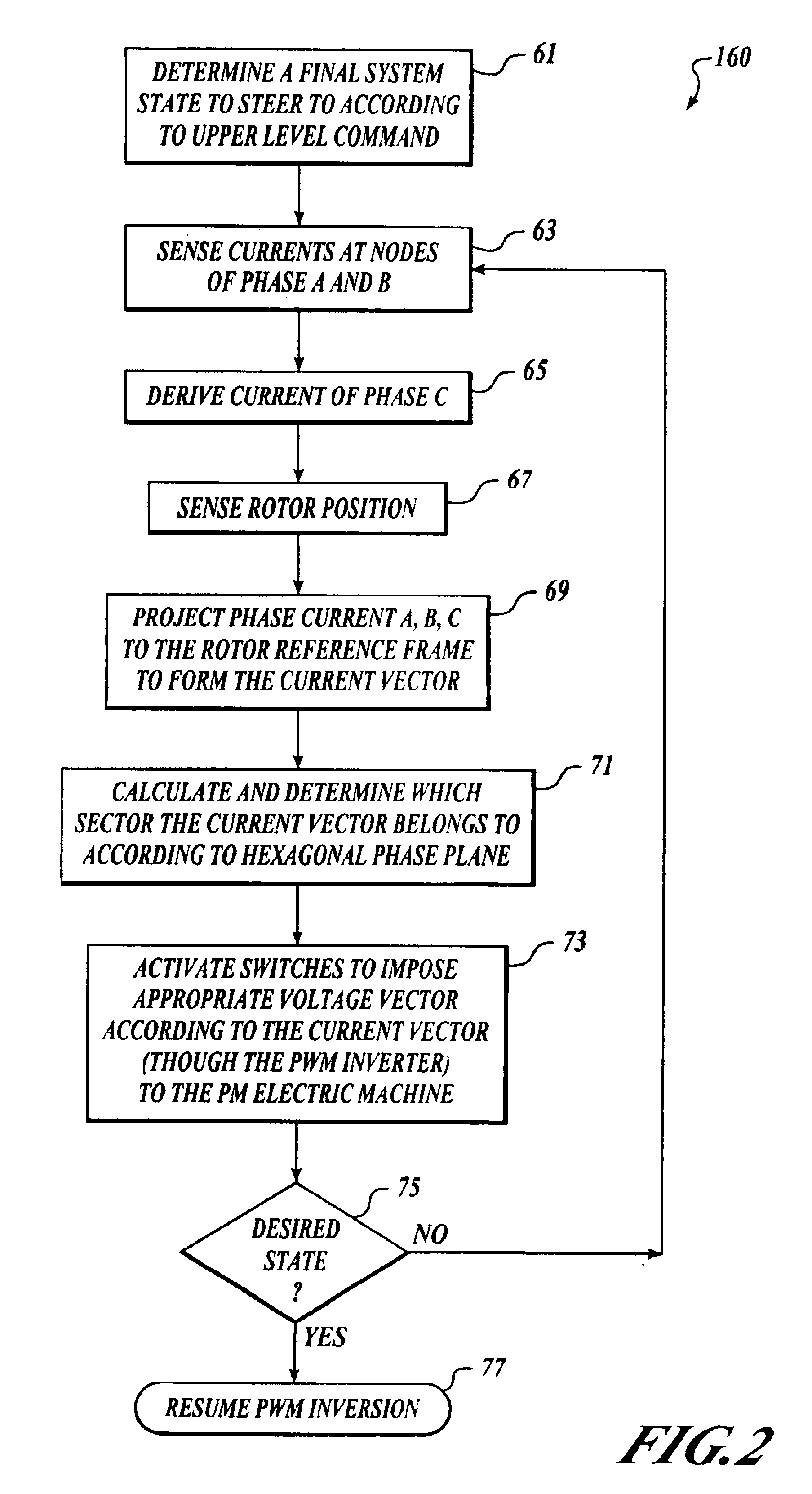
[0023]By way of overview, a method for driving a neutral point-clamped three-level voltage source inverter supplying a synchronous motor is provided. A DC current is received at a neutral point-clamped three-level voltage source inverter. The inverter has first, second, and third output nodes. The inverter also has a plurality of switches. A desired speed of a synchronous motor connected to the inverter by the first second and third nodes is received by the inverter. The synchronous motor has a rotor and the speed of the motor is defined by the rotational rate of the rotor. A position of the rotor is sensed, current flowing to the motor out of at least two of the first, second, and third output nodes is sensed, and predetermined switches are automatically activated by the inverter responsive to the sensed rotor position, the sensed current, and the desired speed.

[0024]Referring to FIG. 1 DC linking capacitors 13 and 15 are connected in series and separate a positive DC bus node 11 f...


PUM


Abstract

A method for driving a neutral point-clamped multi-level voltage source inverter supplying a synchronous motor is provided. A DC current is received at a neutral point-clamped multi-level voltage source inverter. The inverter has first, second, and third output nodes. The inverter also has a plurality of switches. A desired speed of a synchronous motor connected to the inverter by the first second and third nodes is received by the inverter. The synchronous motor has a rotor and the speed of the motor is defined by the rotational rate of the rotor. A position of the rotor is sensed, current flowing to the motor out of at least two of the first, second, and third output nodes is sensed, and predetermined switches are automatically activated by the inverter responsive to the sensed rotor position, the sensed current, and the desired speed.

Description

GOVERNMENT RIGHTS[0001]This invention was made with Government support under contract number DE-PS36-97G00231 awarded by the Department of Energy. The government has certain rights in this invention.FIELD OF THE INVENTION[0002]This invention relates generally to power conversion and, more specifically, to multi-level inverter modulation.BACKGROUND OF THE INVENTION[0003]Voltage source inverters are utilized in AC motor drive, utility interface, and an uninterruptible power supply (“UPS”) applications as a means for converting DC to AC electrical power. A traditional voltage source inverter generates a low frequency output voltage with controllable magnitude and frequency by programming high-frequency voltage pulses. The high frequency voltage pulses open and close switches to expose a load to pulses of DC current. An inverter of this type is said to be using pulse width modulation (“PWM”). Timing, duration, and voltage of the pulses simulate the peaks and troughs of traditional sinus...

Claims


Application Information

Patent Timeline
IPC IPC(8): H02M7/162H02M7/487H02P1/46
CPCH02M7/487
Inventor EDWARDS, JOHNXU, LONGYABHARGAVA, BRIJ B.
Owner THE BOEING CO
Why Eureka
Try Eureka