Generator with dual cycloconverter for 120/240 VAC operation

a cycloconverter and generator technology, applied in the direction of transportation and packaging, d ac network circuit arrangement, etc., can solve the problems of increasing coil resistance, reducing system efficiency, and not enough voltage “head room” is required

Inactive Publication Date: 2006-09-05
BLACK & DECKER INC
View PDF73 Cites 32 Cited by
  • Summary
  • Abstract
  • Description
  • Claims
  • Application Information

AI Technical Summary

Benefits of technology

[0028]In an aspect of the invention, the permanent magnet generator has rotor position sensors that sense the position of a rotor of the permanent magnet generator as it rotates. Outputs of these rotor position sensors are input to the controller which uses them to generate control wave information that it uses to control the cycloconverters, illustratively cosine control wav...

Problems solved by technology

However, sufficient voltage “head room” is still required.
This higher voltage requires more turns in the alternator coils resulting in an increased coil resistance and reduced system efficiency.
A sine wave pulse width modulated (PWM) inverter will produce excellent waveforms with only some high frequency noise, but they are likely to require full H-bridges which, traditionally, have not been easily adaptable to the North American grounding convention and the 4-blade twist-lock wiring convention.
However, trying to produce sine waves from a two half bridge circuit may require large capacitors that would reduce the benefit of volume reduction provided by the inverter topology.
However, permanent magnet generators provide a very soft...

Method used


Image

  • Generator with dual cycloconverter for 120/240 VAC operation
  • Generator with dual cycloconverter for 120/240 VAC operation
  • Generator with dual cycloconverter for 120/240 VAC operation

Examples


Embodiment Construction

[0044]The following description of the preferred embodiment(s) is merely exemplary in nature and is in no way intended to limit the invention, its application, or uses.

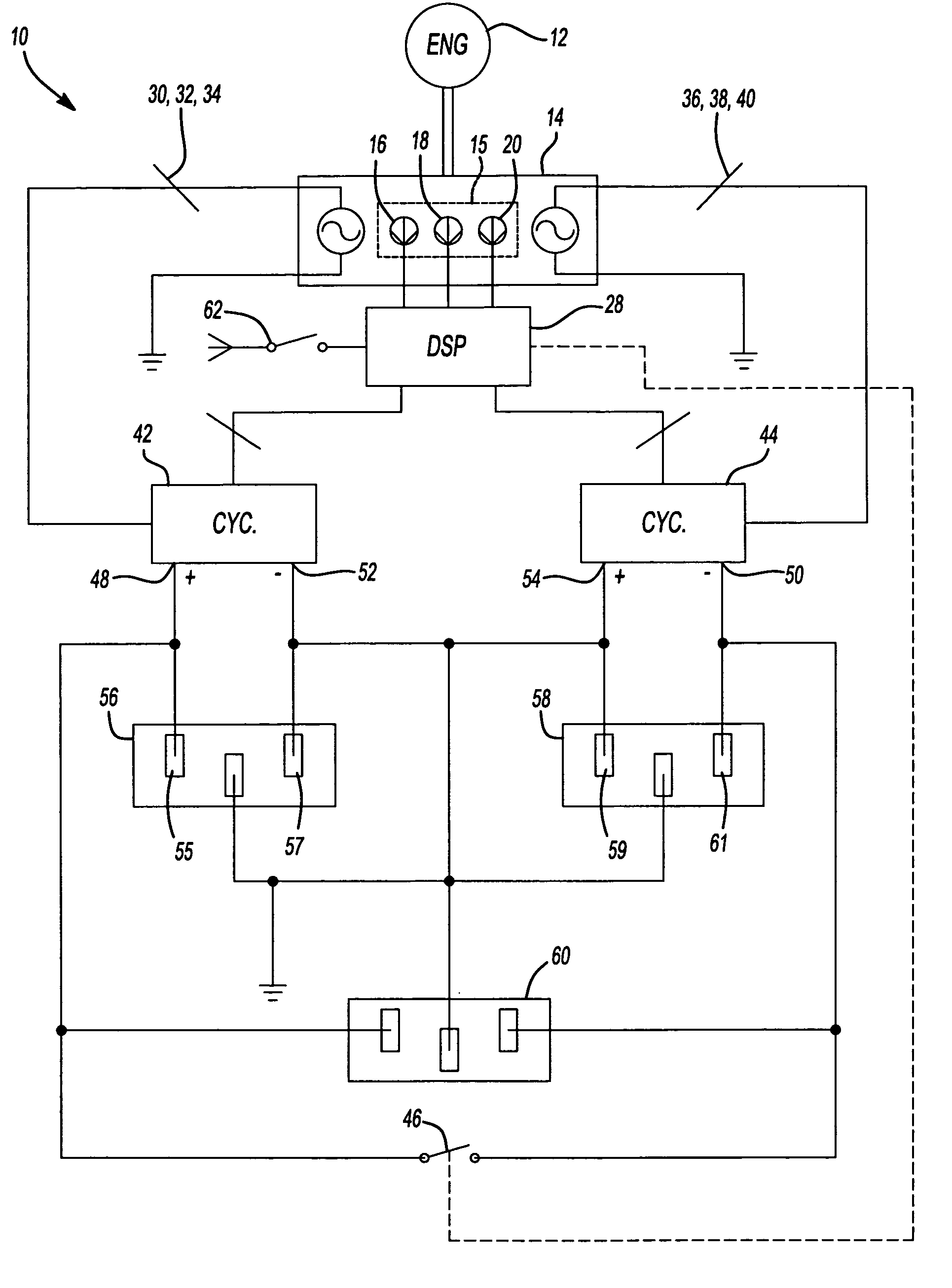
[0045]Referring to FIG. 1, a generator system 10, switchable between first and second modes of operation is shown schematically. In the first mode, the generator system 10 produces a first output voltage and in the second mode, the generator system 10 produces two output voltages, the first output voltage and a second output voltage that is twice the first output voltage. In an embodiment, the first output voltage is nominally 120 VAC and the second output voltage is 240 VAC and the first mode is then alternatively referred to as the 120 VAC mode and the second mode is alternatively referred to as the 240 / 120 VAC mode. In this embodiment, the first output voltage is referred to as being nominally 120 VAC to mean that it is the standard AC voltage used in the United States for light appliances and devices, such as lamp...


PUM


Abstract

A generator system in accordance with the invention has two modes of operation, such as 120 VAC and 240/120 VAC modes of operation. The generator system has a permanent magnet generator with two independent sets of windings that each generate a three phase AC voltage. One three phase AC voltage is coupled to a first or master cycloconverter and the second three phase AC voltage is coupled to a second or slave cycloconverter. Live outputs of each cycloconverter are coupled to each other through a switch, such as a relay and neutral outputs of each cycloconverter are coupled to ground. A controller controls the cycloconverters to provide a first voltage, illustratively 120 VAC, across their respective outputs having the same amplitude. When in the 120 VAC mode, the switch across the live outputs of the first and second cycloconverters is closed, shorting the live outputs of the first and second cycloconverters together and the controller operates the first and second cycloconverters so their output voltages are in phase with each other. When in the 240/120 VAC mode, the switch across the live outputs of the first and second cycloconverters is open and the controller operates the first and second cycloconverters so that their output voltages are 180 degrees out of phase. The permanent magnet generator has rotor position sensors that are used by a brushless DC motor drive to drive the permanent magnet generator as a brushless DC motor to start the engine of the generator system and also to develop cosine wave information for use in controlling the cycloconverters.

Description

CROSS-REFERENCE TO RELATED APPLICATIONS[0001]This application claims the benefit of U.S. Provisional Application No. 60 / 440,959, filed on Jan. 17, 2003.FIELD OF THE INVENTION[0002]The present invention relates to portable generators, and more particularly, a portable generator using cycloconverters that has a 120 VAC mode of operation and a 240 / 120 VAC mode of operation.BACKGROUND OF THE INVENTION[0003]Present day portable generators typically make use of a synchronous alternator or cycloconverter for providing the desired power output, which is typically 120 VAC or 240 VAC. Important considerations for any portable generator are:[0004]Voltage regulation;[0005]Dual voltage output capability;[0006]Idle voltage and frequency;[0007]Frequency tolerance;[0008]Harmonic distortion:[0009]Induction motor operation[0010]Charger operation[0011]Grounding configuration;[0012]4-blade (120–240 volt) twist-lock compatibility;[0013]Response to load changes; and[0014]Size and weight.[0015]With regard...

Claims


Application Information

Patent Timeline
IPC IPC(8): H02J1/00H02J7/00H02J7/14H02J7/24H02M5/22
CPCH02M5/22
Inventor WALTER, RICHARD T.FORSTER, MICHAEL K.
Owner BLACK & DECKER INC
Why Eureka
Try Eureka