
Continuous wave pumped parallel fiber optical parametric amplifier

a parallel fiber optical and parallel fiber technology, applied in optics, instruments, electromagnetic transmission, etc., can solve the general lack of flatness of the available gain bandwidth, and achieve the effect of suppressing crosstalk due to conjugate generation and high gain

Inactive Publication Date: 2006-09-05
ERICSSON TELECOMMUNICACOES SA
View PDF9 Cites 3 Cited by
  • Summary
  • Abstract
  • Description
  • Claims
  • Application Information

AI Technical Summary

Benefits of technology

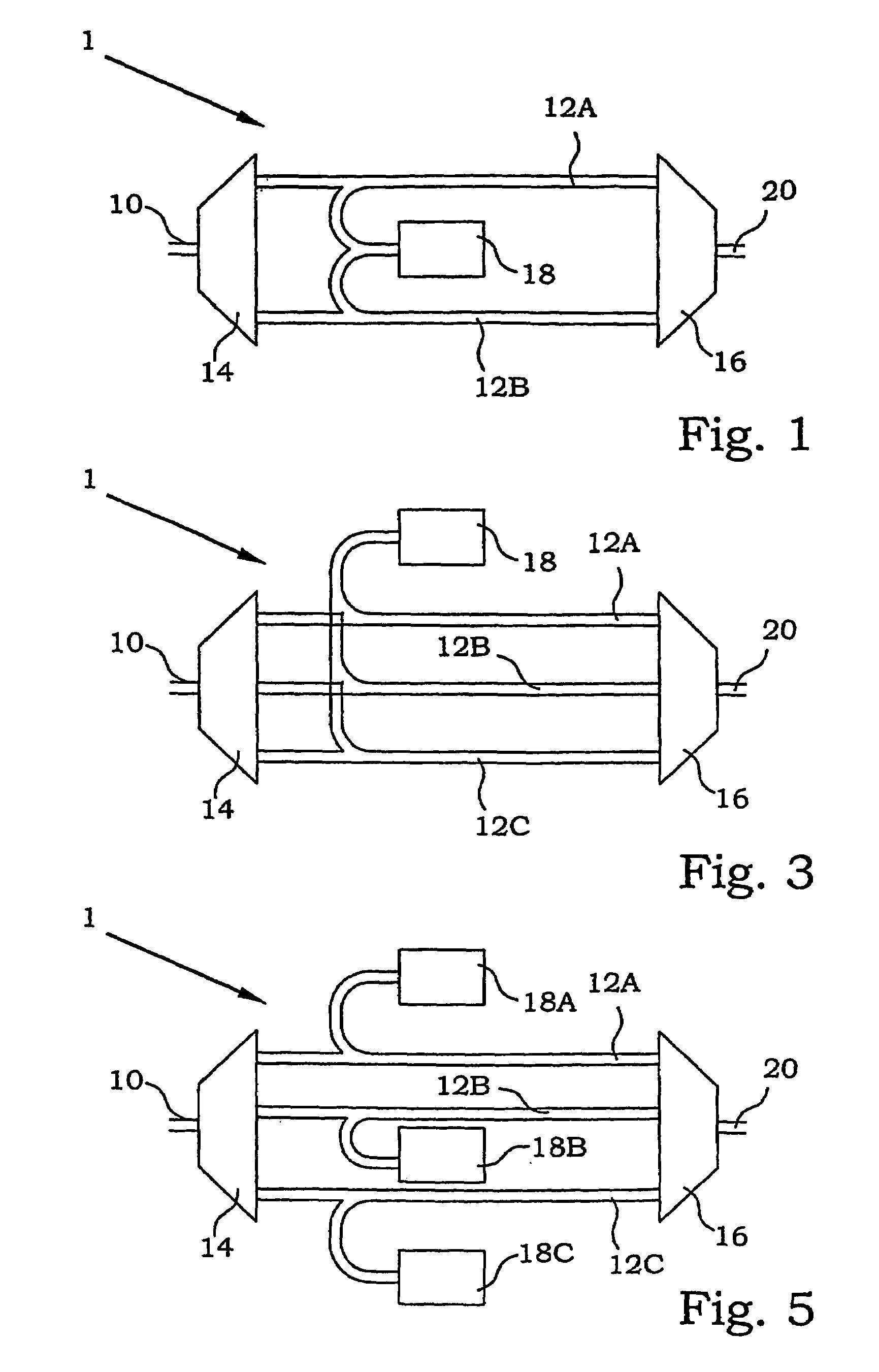
"The present invention provides a parametric amplifier device and method with improved suppression of crosstalk, giving amplification in a wide frequency band. The device has a gain flatness sufficient for e.g. wavelength division multiplexing applications and produces high gains, preferably over 20 dB over wide bandwidths. The amplifiers should preferably be operable in any spectral region within the low-loss band of optical fibers. The invention achieves this by configuring a number of nonlinear optical fibers in a parallel configuration and pumping them with optical pumps having a wavelength slightly longer than the zero dispersion wavelength for each fiber. By selecting the admitted wavelength intervals, crosstalk due to conjugated signals with respect to the pump wavelength will be suppressed. The nonlinear fibers can be pumped by separate laser pumps or two or more of the nonlinear fibers can be pumped by the same pump, depending on the different fiber properties. The amplifiers are used in WDM or DWDM systems. The present invention practically eliminates crosstalk and achieves high gains in a wide bandwidth range."

Problems solved by technology

One common problem with parametric amplifier solutions according to prior-art is according to previous discussions potential crosstalk from four-wave mixing products.
Moreover, there is a general lack of flatness of the available gain bandwidth, calling for extra flattening devices.

Method used


Image

  • Continuous wave pumped parallel fiber optical parametric amplifier
  • Continuous wave pumped parallel fiber optical parametric amplifier
  • Continuous wave pumped parallel fiber optical parametric amplifier

Examples


Embodiment Construction

[0032]In the present invention, it will be demonstrated a new scheme employing parallel configuration, which makes it possible to reduce crosstalk. The same scheme may be further utilized to expand the useful bandwidth. Even using commercially available optical fibers, with the highest nonlinearity they allow, it will be shown that with the present scheme a much greater bandwidth is possible.

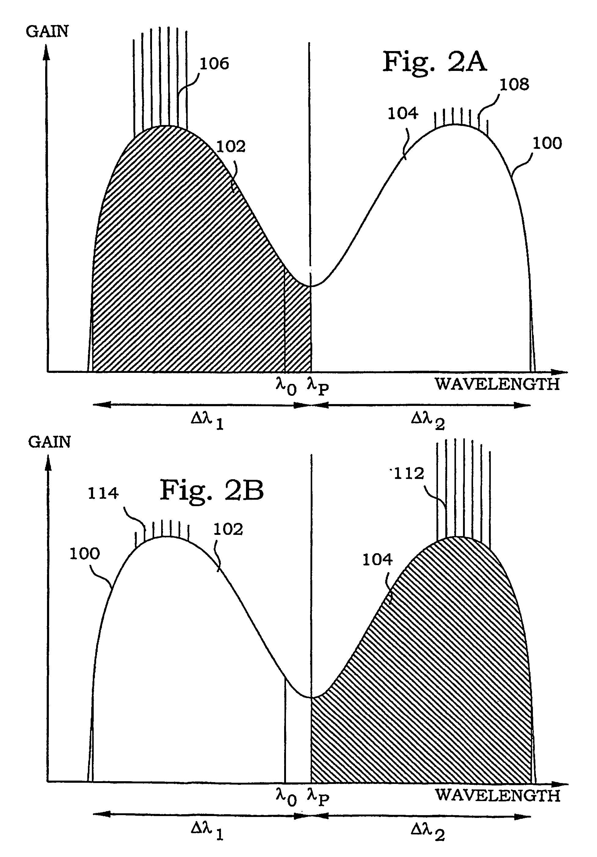
[0033]The basic operation principle of fiber optical parametric amplifiers is known in prior art. An optical fiber is used, having nonlinear properties. Due to four-wave mixing, a high-intensity optical signal may be transferred into optical signals having a different wavelength. If one specific frequency is applied to a nonlinear optical fiber, the sideband frequencies may build up from noise under the proper circumstances. The optimum operational condition occurs when the pump wavelength is slightly longer than the zero dispersion wavelength of the nonlinear fiber. Gain spectra are approximate...


PUM

PropertyMeasurementUnit
zero dispersion wavelengthaaaaaaaaaa
zero dispersion wavelength λ0aaaaaaaaaa
pump wavelength λPaaaaaaaaaa

Abstract

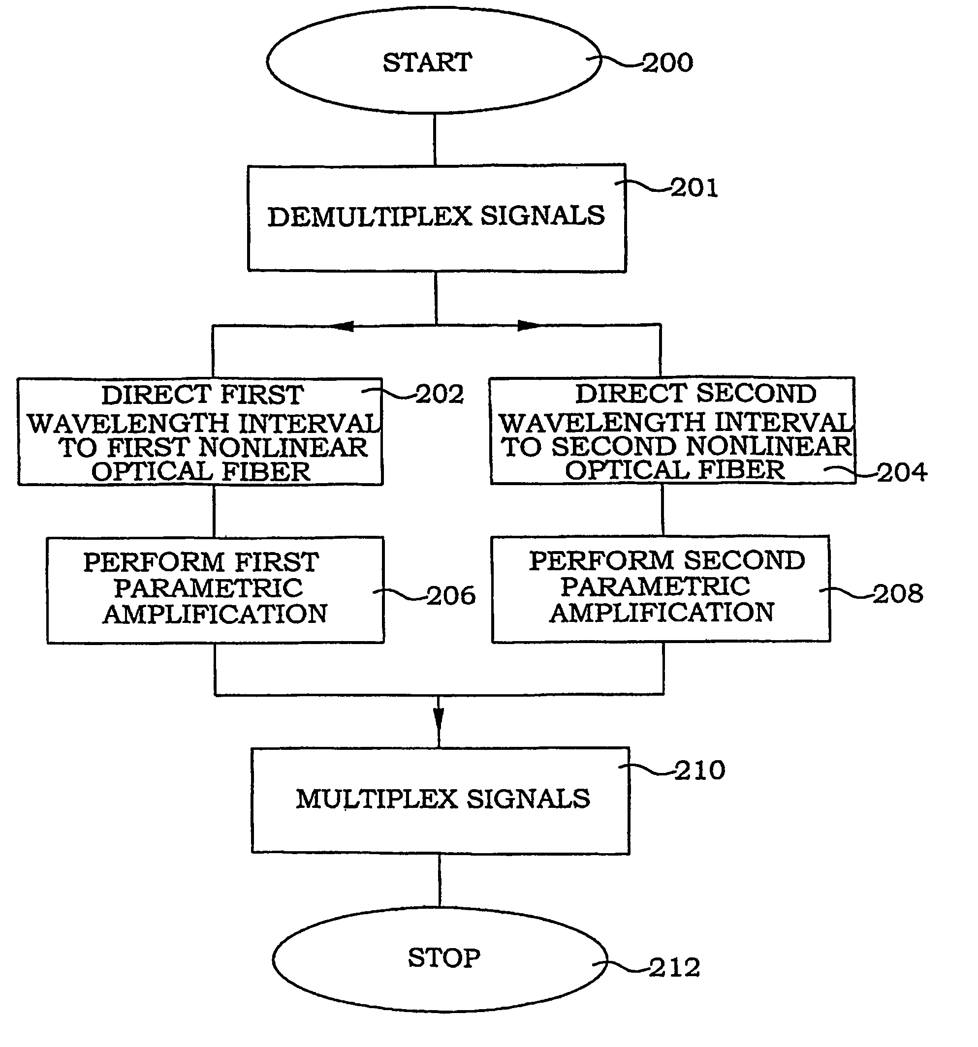
A number of nonlinear optical fibers are configured in a parallel configuration. The fibers are pumped with optical pumps having a wavelength slightly longer than the zero dispersion wavelength for each fiber. By a demultiplexer optical signals within a certain wavelength interval are admitted to enter and exit the different fibers, in which parametric amplification can be achieved. By selecting the pump wavelength outside each corresponding interval crosstalk will be suppressed. The nonlinear fibers can be pumped by separate laser pumps, or two or more of the nonlinear fibers can be pumped by a common pump, depending on the different fiber properties. By tailoring fiber properties such as the zero dispersion wavelength, the second order dispersion coefficient and the fourth order dispersion coefficient, beneficial amplification characteristics can be achieved in different wavelength intervals.

Description

[0001]This application is the U.S. national phase of international application PCT / BR2002 / 000174, filed 5 Dec. 2002 which designated the U.S. and claims benefit of same, the entire contents of which are hereby incorporated by reference.TECHNICAL FIELD[0002]The present invention relates in general to optical fiber amplifiers and in particular to parametric amplifiers with suppressed crosstalk.BACKGROUND[0003]Data communication of different kinds becomes more and more frequent today. This development demands higher bandwidth available for the communication. The capacity of different types of telecommunication systems has increased tremendously during the last decade. An increasing part of the capacity is supplied by optical fibers that present bandwidth enhancements of several magnitudes compared with ordinary wires.[0004]The bandwidth of optical fibers is used in an efficient manner by employing Wavelength Division Multiplexing (WDM) techniques. Many channels using a multitude of sli...

Claims


Application Information

Patent Timeline
Patent Type & Authority Patents(United States)
IPC IPC(8): H01S3/067G02F1/39H01S3/00H01S3/094H01S3/108H01S3/23H04B10/17
CPCG02F1/395H01S3/06754H04B10/2972H01S3/1083H01S3/005H01S3/06725H01S3/094061H01S3/2383H01S3/094003
Inventor GOMES, ANDERSONFLORIDA, CLAUDIOSUNDHEIMER, MICHAELDE BARROS, MIRIAM R. X.ROSOLEM, JOAO B.
Owner ERICSSON TELECOMMUNICACOES SA
Learn More