
Optical pickup apparatus and objective lens

a pickup device and optical technology, applied in the field of objective lenses, can solve the problems of difficult to make f smaller than the present value, difficult to realize the effect of objective lenses and optical pickup devices having sufficient optical performance, and achieve excellent temperature characteristics

Inactive Publication Date: 2006-09-05
KONICA CORP
View PDF19 Cites 10 Cited by
  • Summary
  • Abstract
  • Description
  • Claims
  • Application Information

AI Technical Summary

Benefits of technology

"The patent text explains how to correct temperature-related aberrations in a resin aspherical single lens used in optical information recording devices. By introducing a diffracting power into the lens, the refracting power can be properly allocated between the two, resulting in improved temperature correction. The text also explains the various factors that affect the change in spherical aberration caused by temperature changes, such as the refractive power and the diffracting power. Overall, the patent text provides a technical solution for improving the performance of resin aspherical single lenses in optical information recording devices."

Problems solved by technology

However, an objective lens made of resin materials has a problem that aberration caused by a change in a refractive index that is derived from a temperature change is greater than that of a lens made of glass materials.
Though it is considered to make focal length f to be small for the purpose of keeping the wave front aberration small based on the expression (1), in this case, it is difficult to make f to be smaller than the present value, because it is actually necessary to secure a distance of focusing operation.
However, an objective lens which is made of plastic and satisfies various performances necessary for an optical pickup device, and an optical pickup device employing such objective lens made of plastic are not on practical use, and studies for them have not made yet.
On the other hand, in the case of a lens system using a conventional objective lens made of resin materials, there has been generated aberration that is proportional to the fourth power of numerical aperture NA of the objective lens on the image side, and is caused by refractive index change An of resin material derived from a temperature change, and this aberration has made it difficult to realize an objective lens and an optical pickup device both having sufficient optical performances.
Therefore, there is a tendency that temperature characteristics are deteriorated more as a movement toward an objective lens for high NA and a movement toward the finite of the objective lens are advanced, or as a movement toward a short wavelength of a laser light source is advanced.
However, when trying to improve temperature characteristics by employing diffraction, following two troubles are caused.
First one of these troubles is that an objective lens turns out to be weak for wavelength characteristics.
The second trouble is that when trying to make the effectiveness of diffraction to be great, diffraction pitch becomes small and diffraction efficiency is lowered.

Method used


Image

  • Optical pickup apparatus and objective lens
  • Optical pickup apparatus and objective lens
  • Optical pickup apparatus and objective lens

Examples


first embodiment

(First Embodiment)

[0480]First embodiment will be explained as follows. FIG. 5 is a schematic structure diagram of an optical pickup device. In optical pickup device 100 shown in FIG. 5, a light flux emitted from semiconductor laser 111 representing a light source passes through beam splitter 120 representing a light merging means, then, stopped down by diaphragm 17 to the prescribed numerical aperture, and forms a spot on information recording surface 220 through diffraction-integrated objective lens 160 and through transparent base board 210 of high density recording optical disk 200 representing an optical information recording medium. A wavelength (standard wavelength) of the semiconductor laser light is 650 nm.

[0481]A reflected light flux modulated by information bit on information recording surface 220 passes through the diffraction-integrated objective lens 160 again to be changed into a converged light, then, further passes through diaphragm 17 to be reflected on beam splitte...

second embodiment

(Second Embodiment)

[0491]Next, the second embodiment will be explained. This embodiment is one wherein a wavelength of a light source under which DVD is used is different from that under which CD is used, and explanation of portions in this embodiment which are the same as those in the first embodiment will be omitted. In the optical pickup device (that is of a type of two light sources and one detector) related to the present embodiment shown in FIG. 7, there are provided semiconductor laser 111 (designed wavelength λ1=650 nm) representing the first light source for reproducing the first optical disk (DVD) and semiconductor laser 112 (designed wavelength λ1=780 nm) representing the second light source for reproducing the second optical disk (CD).

[0492]First, when reproducing the first optical disk, a beam is emitted from the first semiconductor laser 111, and the light flux thus emitted passes through beam splitter 190 which is a light merging means for light emitted from the semic...

third embodiment

(Third Embodiment)

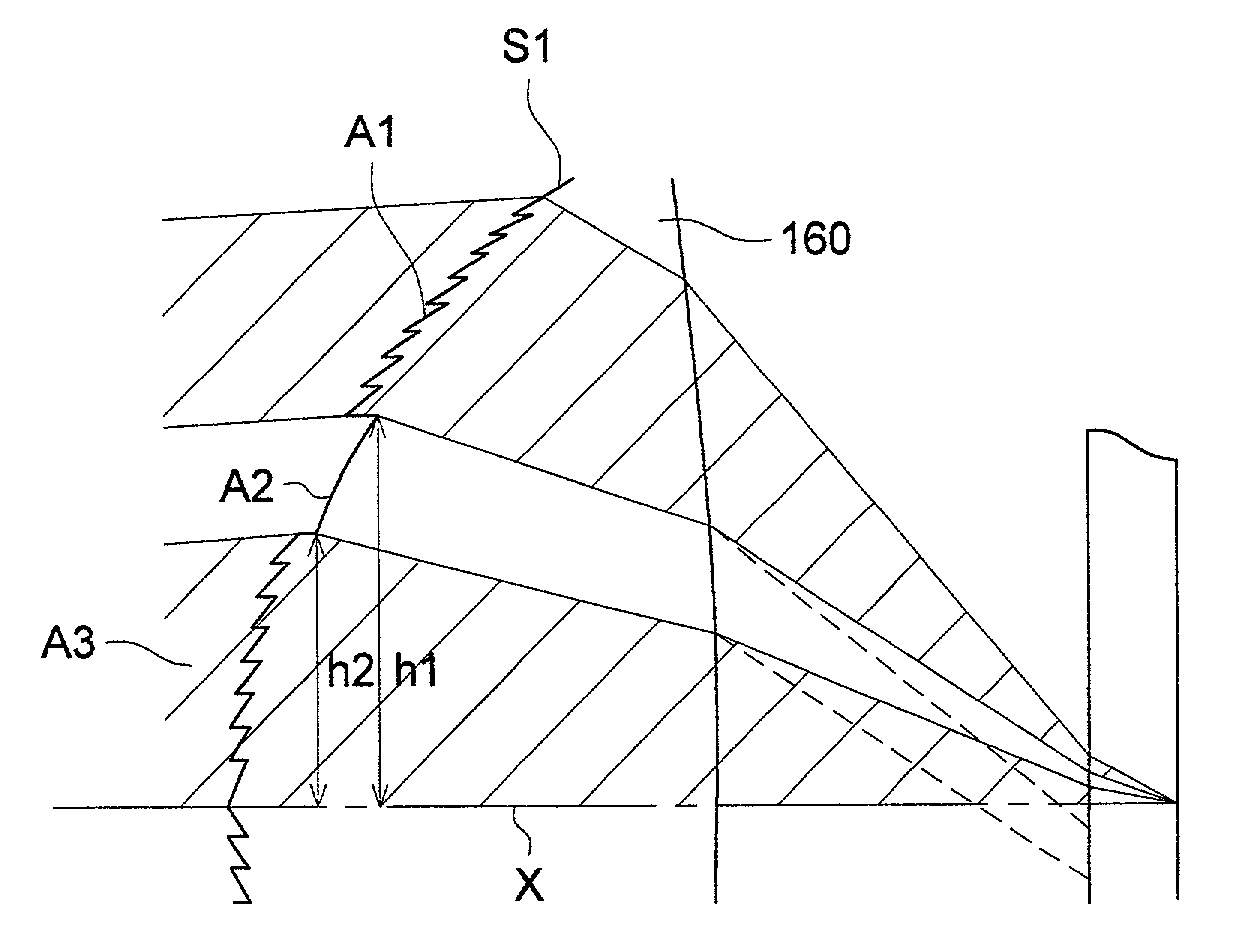
[0503]Next, the third embodiment will be explained. This embodiment is one wherein a wavelength of a light source under which DVD is used is the same as that under which CD is used, and explanation of portions in this embodiment which are the same as those in the aforesaid embodiment will be omitted. An optical pickup device is the same as one shown in FIG. 5 in terms of structure. A schematic structure diagram of an objective lens is shown in FIG. 9.

[0504]On surface S1 of objective lens 160 closer to a light source, there are formed three optical surface areas A1, A2 and A3 each being designed optically based on a different concept. However, from the viewpoint of using a light flux, a light flux passing through the outermost optical surface area A1 and the innermost optical surface area A3 is used to form an optical spot on a recording surface in the case of using DVD, and a light flux passing through the intermediate optical surface area A2 and the innermost opti...


PUM

PropertyMeasurementUnit
wavelengthaaaaaaaaaa
thicknessaaaaaaaaaa
thicknessaaaaaaaaaa

Abstract

An objective lens of an optical pickup apparatus converges a divergent light flux onto an information recording surface. The following conditional formula is satisfied:|δSA1 / δU|·|δU|+|δSA2 / δT|·|δT|≦0.07 λrmswhere λ represents a wavelength of a light source, δSA1 / δU represents a change of a spherical aberration for an object-to-image distance change δU (|δU|≦0.5 mm) and δSA2 / δT represents a change of spherical aberration for a temperature change δT (|δT|≦30° C.), the object-to-image distance is a distance between the light source (a light emitting point) and the information recording surface.

Description

BACKGROUND OF THE INVENTION[0001]The present invention relates to an objective lens of an optical pickup device and to the optical pickup device, and in particular, to an objective lens wherein magnification is finite and yet the temperature characteristics are excellent for recording or reproduction for at least two optical information recording media each having a transparent base board with a different thickness and to an optical pickup device.[0002]With regard to a recording / reproducing optical system for optical information recording media having a precision required for the conventional CD reproducing apparatus (incidentally, a recording / reproducing optical system or a recording / reproducing apparatus mentioned in the present specification includes a recording optical system, a reproducing optical system, a recording and reproducing optical system, and an apparatus employing the foregoing), an infinite conjugated optical system is disclosed in TOKKAISHO No. 57-76512, and a fini...

Claims


Application Information

Patent Timeline
Patent Type & Authority Patents(United States)
IPC IPC(8): G11B7/135G11B7/00
CPCG11B7/1353G11B7/1374G11B7/13922G11B2007/0006G02B13/00
Inventor SAITO, SHINICHIROSAKAMOTO, KATSUYA
Owner KONICA CORP
Features
  • Generate Ideas
  • Intellectual Property
  • Life Sciences
  • Materials
  • Tech Scout
  • Unparalleled Data Quality
  • Higher Quality Content
  • 60% Fewer Hallucinations
Learn More