
Modulated radio signal transmitter with self-adapted amplification polarization

a radio signal and self-adaptive technology, applied in the field of transmitters of radio signals, can solve the problems of low efficiency, low efficiency, and overall electrical consumption, and achieve the effect of simple and inexpensive production and easy application

Inactive Publication Date: 2006-09-05
CENT NAT DETUD SPATIALES C N E S
View PDF9 Cites 57 Cited by
  • Summary
  • Abstract
  • Description
  • Claims
  • Application Information

AI Technical Summary

Benefits of technology

[0012]It is therefore an object of the invention to overcome all these drawbacks and to provide a transmitter as mentioned, and in which at least the output power transistor(s)—in particular all the power transistors—has (have) an efficiency which remains optimized, that is to say it is permanently the best possible, including for low amplitude levels of the input signals, and which is furthermore simple and inexpensive to produce and easy to apply in all carrier-frequency ranges of the signals—including in the microwave range—and in all the variation-frequency ranges of the signals—including for high-speed transmissions.
[0013]It is hence an object of the invention to permit the use of modulation such as amplitude modulation of the quadrature M-QAM type with M states, M being a power of 2, generating modulated signals at the input of the amplification means whose amplitude varies according to a discrete plurality of amplitude levels, without substantially compromising the electrical consumption of the transmitter compared with other types of modulation, in which the amplitude of the input modulated signals remains at least substantially constant, and to do so in a way which is simple, economical and applicable to all the frequency ranges, including microwave carriers and / or high-speed transmissions.

Problems solved by technology

Moreover, such a drop in efficiency is highly detrimental in all applications in which the electrical energy source for supplying the transmitter is not inexhaustible, and is formed in particular by accumulators or cells, and more generally when this electrical energy is expensive.
Such is, in particular, the case on board space systems such as satellites, and more particularly micro-satellites, in which energy and cost economies as well as the problem of simplicity and speed of manufacture are crucial.
This problem is generally encountered for each of the power transistors of the amplification means, but more particularly at least for the output power transistor(s), whose operation largely determines the overall electrical consumption of the transmitter.
This technique is, however, limited by the switching-frequency values and is not therefore easy to apply at very high envelope frequencies, especially in the field of high-speed digital data transmissions (typically several megabits per second or tens of megabits per second between space systems—in particular satellites—and the earth).
Furthermore, production of the envelope detector, the limiter and the converter is relatively complex—especially in the field of high-speed transmissions in which the modulated signals have a microwave carrier.
It is furthermore relatively complex to produce, in particular when the modulated signals have a microwave carrier.
This is because the circuits through which microwave signals travel are known to be complex, expensive and difficult to tune.
This solution therefore tends to amplify the errors and noises and has imprecise operation.

Method used


Image

  • Modulated radio signal transmitter with self-adapted amplification polarization
  • Modulated radio signal transmitter with self-adapted amplification polarization
  • Modulated radio signal transmitter with self-adapted amplification polarization

Examples


Embodiment Construction

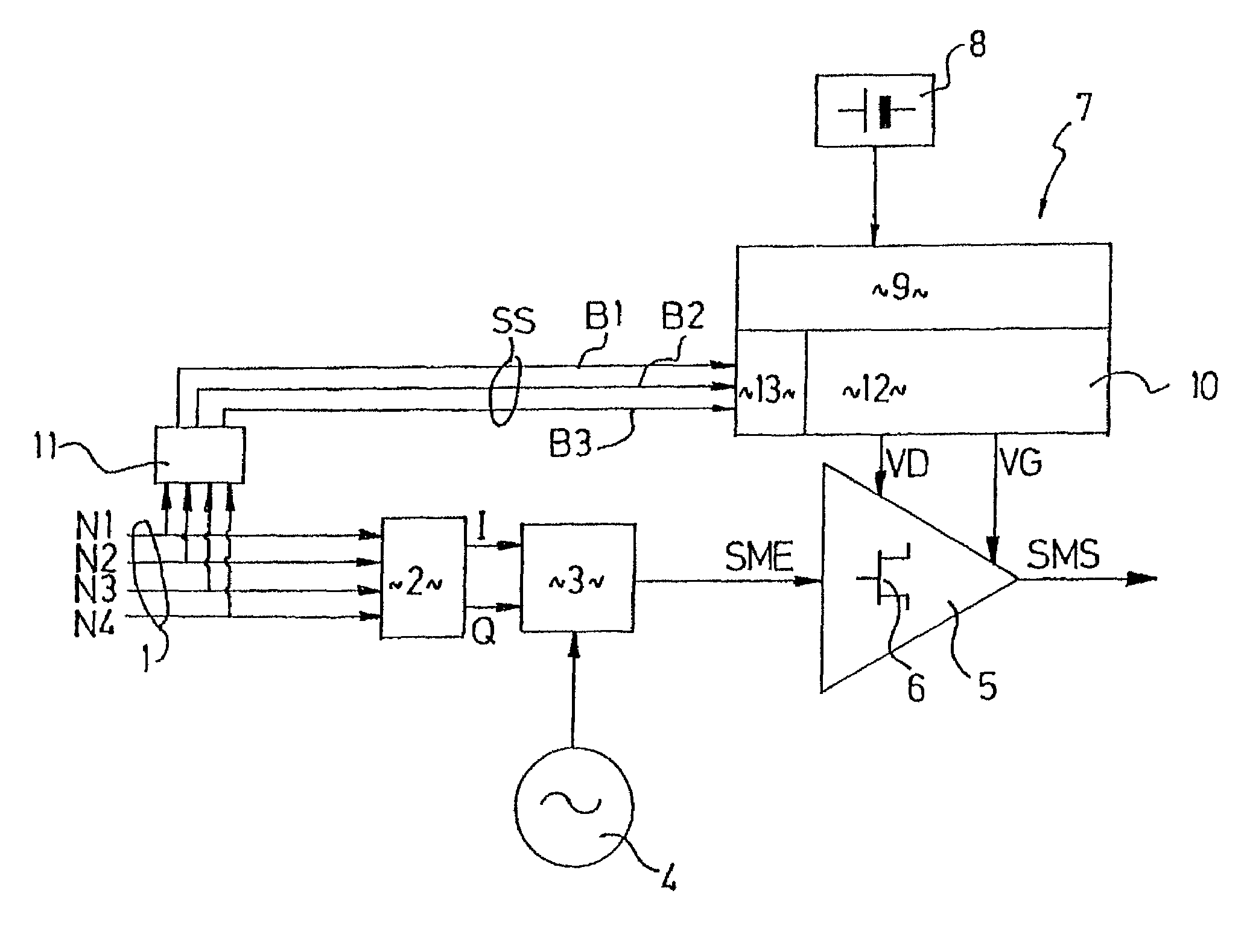
[0044]The transmitter according to the invention schematically represented in FIG. 1 receives digital data to be transmitted, referred to as digital control signals 1, which comprise four bits N1, N2, N3, N4 in the example that is represented. The digital control signals 1 are supplied to a digital / analog converter 2 which delivers two analog signals I, Q in quadrature, which are in turn supplied to a modulator circuit 3 whose output delivers signals, referred to as input modulated signals SME, modulated on a carrier delivered by an oscillator 4 to the modulator circuit 3.

[0045]The input modulated signals SME are supplied to a power amplifier 5 comprising at least one power transistor 6, at least one of which is an output power transistor that delivers output modulated signals SMS supplied to a transmission antenna (not shown).

[0046]Each power transistor 6 of the amplification means 5 is biased by bias means 7 providing the drain bias voltages VD and gate bias voltages VG of the fie...


PUM


Abstract

The invention relates to a transmitter of radio signals (SMS), which are amplitude-modulated according to a discrete plurality of amplitude levels, in which at least one output power transistor (6) receives, on one of its terminals, a bias-voltage level which is adapted to the amplitude level represented by the instantaneous value of a selection signal (SS) generated by analysis means (11) on the basis of the digital control signals (1). The electrical consumption is hence optimized.

Description

BACKGROUND OF THE INVENTION[0001]The invention relates to a transmitter of radio signals, referred to as output modulated signals, which are modulated at least in amplitude according to a discrete plurality of predetermined separate amplitude levels on the basis of digital control signals, comprising,[0002]modulation means adapted to convert the digital control signals into modulated signals, referred to as input modulated signals,[0003]solid-state power amplification means including at least one power transistor, at least one of which is an output power transistor delivering output modulated signals,[0004]bias means including at least one voltage source, and adapted to bias each power transistor of the amplification means.[0005]Transmitters of modulated radio signals have been known for a long time and can be extremely varied. The modulation may be phase and / or amplitude and / or frequency modulation. In the case of amplitude modulation, and also in the case of certain phase modulati...

Claims


Application Information

Patent Timeline
IPC IPC(8): H04L25/06H03F3/24H03F1/02H04B1/04
CPCH03F1/0227H04B1/04H03F1/0261H04B2001/0408H03F3/24
Inventor LAPIERRE, LUC
Owner CENT NAT DETUD SPATIALES C N E S
Learn More