
Register controlled delay locked loop circuit

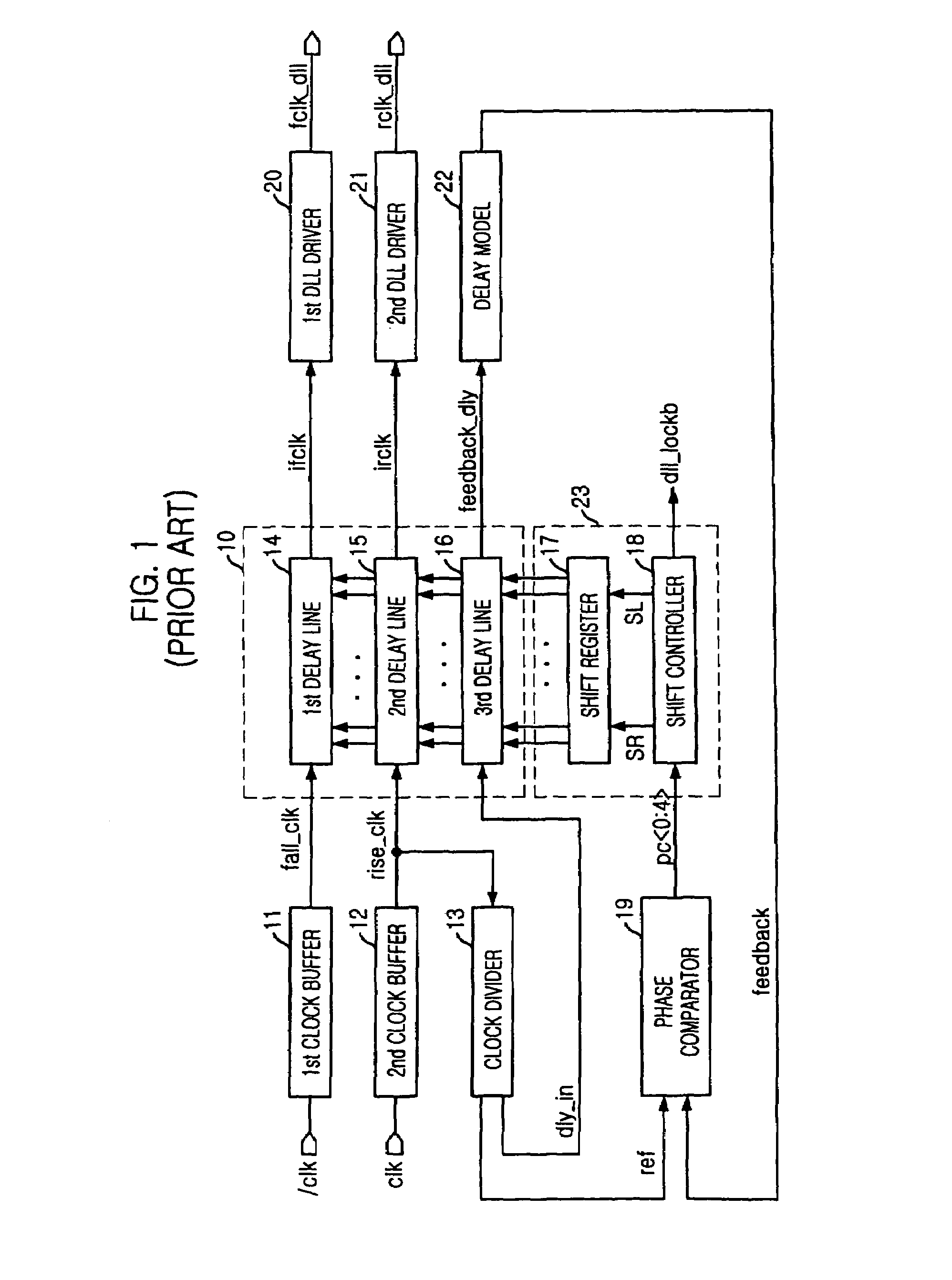
a delay lock and register technology, applied in the direction of digital storage, pulse automatic control, generating/distributing signals, etc., can solve the problems of low electric power consumption and fast operation, clock skew in the circuit, and limited low-power and fast operation

Active Publication Date: 2006-09-05
SK HYNIX INC
View PDF7 Cites 49 Cited by
  • Summary
  • Abstract
  • Description
  • Claims
  • Application Information

AI Technical Summary

Benefits of technology

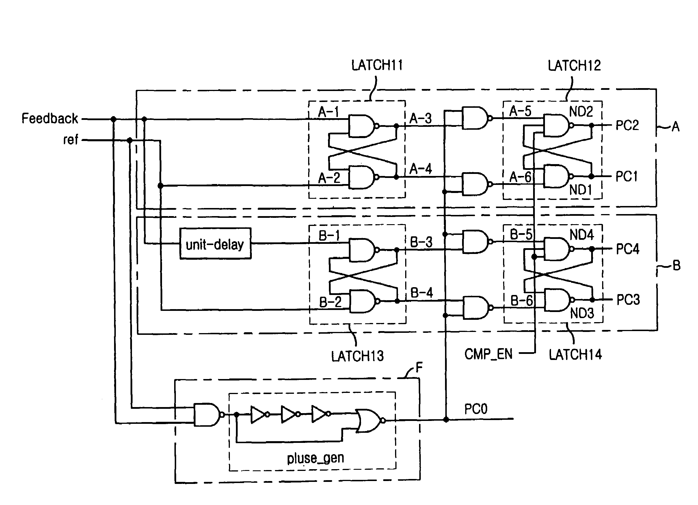
The present invention relates to a register controlled delay locked loop (DLL) circuit and a control method for it. The technical effects of the invention include a smaller area, lower jitter, and faster locking time for a semiconductor device. The invention also provides a method for a self-refresh operation of the DLL to reduce the need for internal clock signals during a self-refresh operation.

Problems solved by technology

When a clock signal from an external clock source is used inside a circuit, a clock skew occurs in the circuit.
These characteristics may still be required for next-generation semiconductor devices that consumes low electric power and operates fast.
However, conventional technologies have fulfilled only a few parts of these requirements, and thus have showed limitations on the low-power and fast operation.

Method used


Image

  • Register controlled delay locked loop circuit
  • Register controlled delay locked loop circuit
  • Register controlled delay locked loop circuit

Examples


Embodiment Construction

[0033]Referring to FIG. 6, the illustrated register controlled delay locked loop (DLL) includes a plurality of inverters 601, 605, 607, 609, 613, 615, 617, 619, a NOR gate 603, and a NAND gate 611.

[0034]A conventional DLL controller located around a shift register 17 outputs a reset signal to the shift register 17 and resets the value contained therein, whenever (a) a DLL performs a self-refresh operation, (b) before power is up, (c) when a signal (disable dll mode) for conducting all operations without using the DLL is received, and (d) when a signal (dll reset mode) for starting a new locking operation is received.

[0035]Accordingly, a reset signal converted into a high state ‘H’ is generated when any one of a signal sref, a signal pwrup, a signal dis_dll, and a signal dll_resetz is used. The signal sref is for maintaining the high state ‘H’ during the self-refresh operation, the signal pwrup is for maintaining the low state ‘L’ before power is up, the signal dis_dll is for maintai...


PUM


Abstract

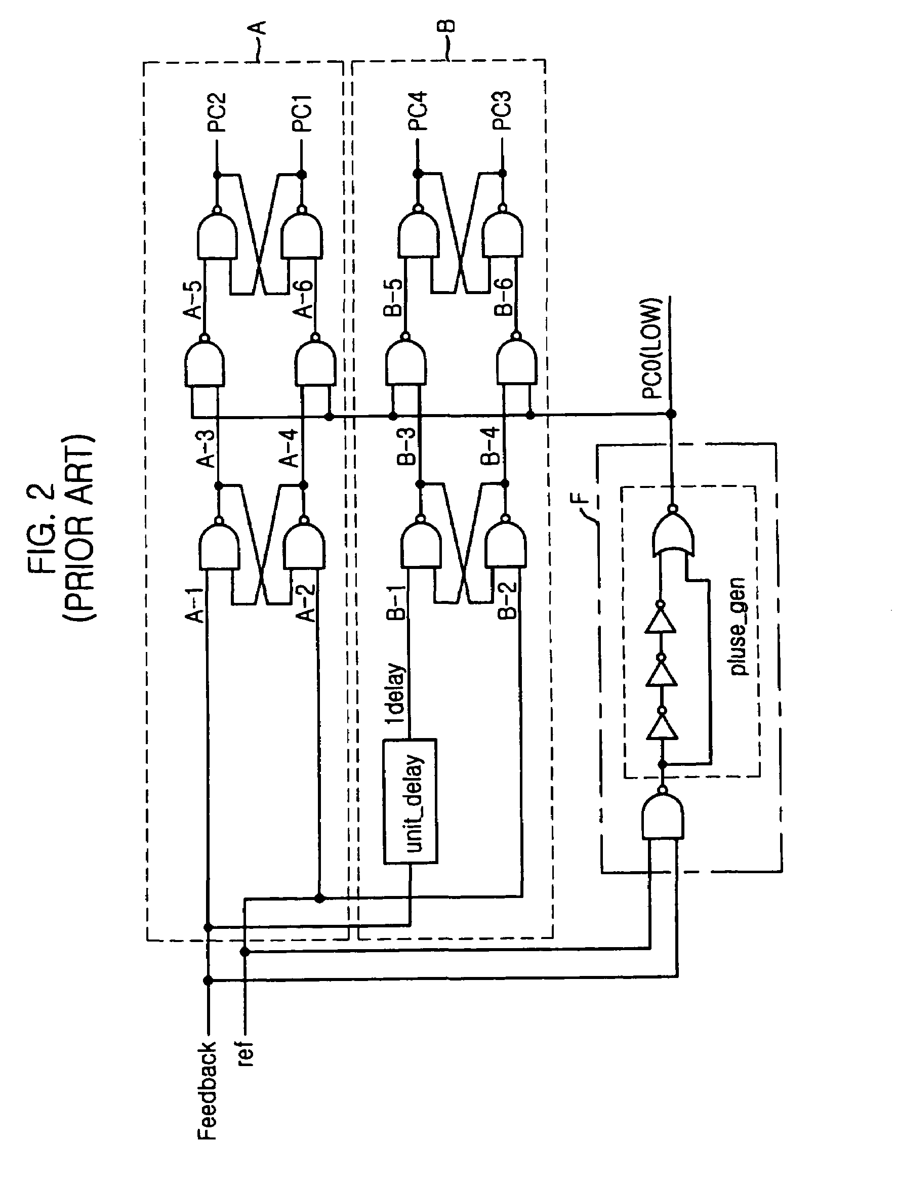
A register controlled delay locked loop (DLL) includes a clock divider, a shift controller, a delay unit and a delay model to synchronize an external clock signal with an internal clock. The register controlled DLL further includes a reset signal generator to generate a reset signal used to initialize the delay locked loop (DLL), a phase comparator to initialize a phase comparison signal in which the phase of a feedback clock signal delayed by a reference clock signal and the delay model is compared and outputted into a predetermined signal by using a comparison enable signal having an inverse phase to that of the reset signal, and a shift register to block an electric current running on a first latch of a plurality of latches with the reset signal during the initialization.

Description

FIELD OF THE INVENTION[0001]The present invention relates to a register controlled delay locked loop (DLL) circuit and a control method thereof.BACKGROUND OF THE RELATED ART[0002]Generally, clock signals are used as a reference for setting the operation timing in a system or a circuit, or they are used to secure fast operation without error. When a clock signal from an external clock source is used inside a circuit, a clock skew occurs in the circuit. Thus, a delay locked loop (DLL) is used to get the internal clock signal to have the same phase as the external clock.[0003]Significant elements required for a DLL are small area, little jitter and fast locking time. These characteristics may still be required for next-generation semiconductor devices that consumes low electric power and operates fast. However, conventional technologies have fulfilled only a few parts of these requirements, and thus have showed limitations on the low-power and fast operation.[0004]Compared with a phase...

Claims


Application Information

Patent Timeline
Patent Type & Authority Patents(United States)
IPC IPC(8): H03D3/24H03L7/06G06F1/04G11C8/00G11C11/00G11C11/403G11C11/407H03K5/135H03L7/081H03L7/10
CPCH03L7/0805H03L7/10H03L7/0814G11C8/00
Inventor JUNG, HEA-SUK
Owner SK HYNIX INC
Learn More