USB eye pattern test mode

a test mode and eye pattern technology, applied in the field of digital systems, to achieve the effect of simple test method, greater degree of confidence and low cos

Inactive Publication Date: 2006-09-05
MICROCHIP TECH INC
View PDF13 Cites 7 Cited by
  • Summary
  • Abstract
  • Description
  • Claims
  • Application Information

AI Technical Summary

Benefits of technology

[0005]The present invention overcomes the above-identified problems as well as other shortcomings and deficiencies of existing technologies, by providing a simple way of injecting USB state transitions on a circuit board and using conventional test equipment to analyze the USB eye pattern signal quality for USB high-speed, USB full-speed, and / or USB low-speed operation.
[0006]According to this disclosure, a special test mode is incorporated within a USB transceiver of a digital system. When the special test mode is activated, a continuous stream of USB state transitions (defined by the USB specification) may be observed on the USB data lines (e.g., USB eye pattern test data signal waveforms). When the USB transceiver is in the special test mode, the signal levels conform to the USB specification. This special test mode signal test pattern, however, violates the USB specification so the special test mode is not used when the USB transceiver is attached to a USB host. However, when the special test mode is in progress, conventional test equipment may be attached to the USB data lines of the USB transceiver and the signal quality thereof monitored. Circuit changes can be made to the digital system and the results easily measured. When the continuous stream of USB state transitions, i.e., USB eye pattern, on the USB data lines of the digital system are of satisfactory quality, this special test mode of the present invention may be disabled and the USB transceiver will resume operation as a normal USB device. The digital system may have a digital processor, e.g., microprocessor, microcontroller, digital signal processor (DSP), application specific integrated circuit (ASIC), programmable logic array (PLA), and the like.
[0010]One technical advantage is that during testing of the USB interface in a digital system, conventional test equipment may be used to trouble shoot and verify satisfactory operation of the circuit under test. This allows a greater degree of confidence in the digital system circuit design and layout of the USB circuit before the complete USB IF is executed for final validation of the USB circuit of the digital system. Another technical advantage is that the test method is simple and inexpensive, and may be performed by relatively unsophisticated testing personnel. Another technical advantage is that no special test equipment is required to validate the quality of the circuit and layout design of a digital system or subassembly running USB.

Problems solved by technology

This special test mode signal test pattern, however, violates the USB specification so the special test mode is not used when the USB transceiver is attached to a USB host.

Method used


Image

  • USB eye pattern test mode
  • USB eye pattern test mode
  • USB eye pattern test mode

Examples


Embodiment Construction

[0016]Referring now to the drawings, the details of exemplary embodiments of the present invention are schematically illustrated. Like elements in the drawings will be represented by like numbers, and similar elements will be represented by like numbers with a different lower case letter suffix.

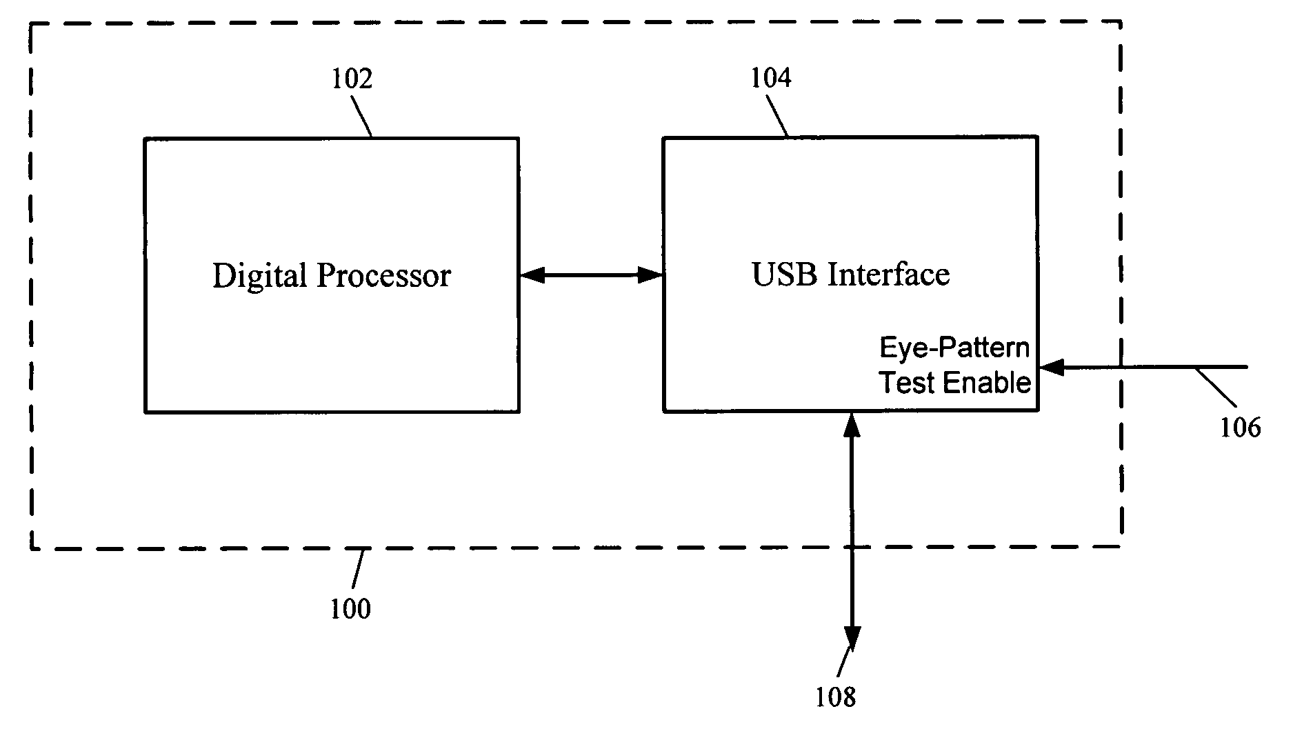
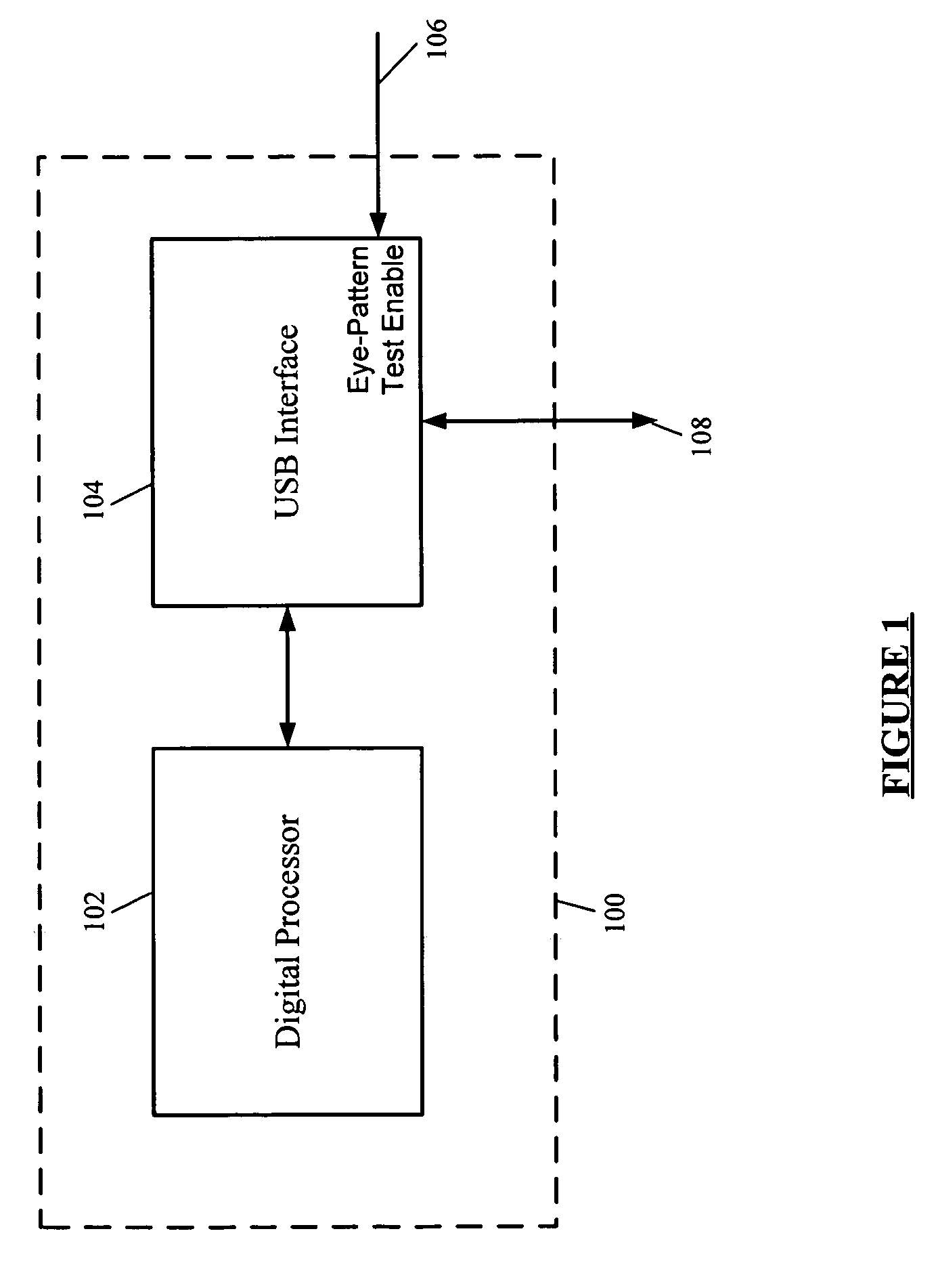
[0017]Referring to FIG. 1, depicted is a schematic block diagram of a digital system having a USB interface with a test mode feature. The digital system, generally represented by the numeral 100, comprises a digital processor 102 and a USB interface 104 mounted on a printed circuit board (not shown). The USB interface 104 has an eye-pattern test enable control line 106 wherein when the control line 106 is at a first logic level, e.g., a logic “1” or logic “0,” the USB interface produces USB signals on the USB data lines 108 that conform to the USB specification. When the control line 106 is at a second logic level, e.g., a logic “0” or logic “1,” the USB interface 104 produces USB eye pattern...


PUM


Abstract

A special test mode is incorporated within a USB transceiver of a digital system, and when the special test mode is activated, USB eye pattern test data signal waveforms, e.g., a continuous stream of USB state transitions (defined by the USB specification) are transmitted on the USB data lines connected to the USB transceiver. Conventional test equipment may be attached to the USB data lines and the signal quality monitored. Circuit changes can be made to the digital system and the results easily measured. When the USB eye pattern test data signal waveforms on the USB data lines of the digital system are of satisfactory quality, the special test mode may be turned off and the USB transceiver will resume operation as a normal USB device.

Description

RELATED PATENT APPLICATION[0001]This application claims priority to commonly owned U.S. Provisional Patent Application Ser. No. 60 / 574,565; filed May 26, 2004; entitled “USB Eye Pattern Test Mode,” by Joseph Julicher, Daniel Butler and Reston Condit; which is hereby incorporated by reference herein for all purposes.TECHNICAL FIELD OF THE INVENTION[0002]The present disclosure relates to digital systems, more particularly, to testing of a Universal Serial Bus (USB) interface in a digital system.BACKGROUND OF THE RELATED TECHNOLOGY[0003]The USB specification calls for very tight control of the electrical signaling on the USB cable. USB is generally described at www.usb.org. Specialized testing fixtures and methods used for validating USB signal integrity (USB IF test) is generally described at http: / / www.usb.org / developers / compliance / . The USB IF test involves a lengthy and expensive data collection system.[0004]Therefore, there is a need for a simpler and lower cost test that may be c...

Claims


Application Information

Patent Timeline
Patent Type & Authority Patents(United States)
IPC IPC(8): G01R27/28G06F11/00G06F11/26G06F11/267
CPCG06F11/221
Inventor JULICHER, JOSEPH HARRYBUTLER, DANIEL WILLIAMCONDIT, RESTON A.
Owner MICROCHIP TECH INC
Why Eureka
Try Eureka