Method employing high kinetic energy for working of material

a high-kinetic energy and material technology, applied in the direction of drilling machines and methods, forging hammers, presses, etc., can solve the problems of excessive tool wear and undesirable burrs, undesirable and in most cases distinctly harmful, and the disadvantage of subjecting the workpiece to be worked in a high-speed process to more than one impact, and achieve the effect of high kinetic energy

Inactive Publication Date: 2006-09-12
CELL IMPACT +1
View PDF11 Cites 7 Cited by
  • Summary
  • Abstract
  • Description
  • Claims
  • Application Information

AI Technical Summary

Benefits of technology

[0004]It is an object of the present invention to eliminate or at least minimize the abovementioned problems, which is achieved by a method for material working utilizing high kinetic energy, comprising a non-oscillating stamp means which is driven from a starting position by an applied force for the purpose of by means of a single blow, transferring high kinetic energy to a material body whi...

Problems solved by technology

It has been a common feature of all these machines, irrespective of whether they have used air, oil, springs, air/fuel mixtures, explosives or electric current for acceleration, that in principle an uncontrolled process has been started, which has resulted in the striking body having been accelerated towards a tool, after which the striking body has in some way been returned after a certain time.
These additional impacts, afterblows, are undesirable and in most cases distinctly harmful.
It has therefore been recognized that it is in principle without exception a disadvantage to subject the workpiece to be worked in a high-speed process to more than one impact, irrespective of whether it is cutting, punching, homogeneous forming or powder compacting which is involved.
As far as cutting is concerned, the extra, unnecessary impact(s) can result in excessive tool wear and undesirable burrs.
In the case of punching, smearing, welding, burrs and tool wear can occur.
In homogeneous forming, there is a risk of undesirable material changes taking place, punches can crack and the blank is fixed unnecessarily hard in the die, which results in the pressing-out force increasing with die wear as a consequence.
In powder compacting using soft powders such as, for example,...

Method used


Image

  • Method employing high kinetic energy for working of material
  • Method employing high kinetic energy for working of material
  • Method employing high kinetic energy for working of material

Examples


Embodiment Construction

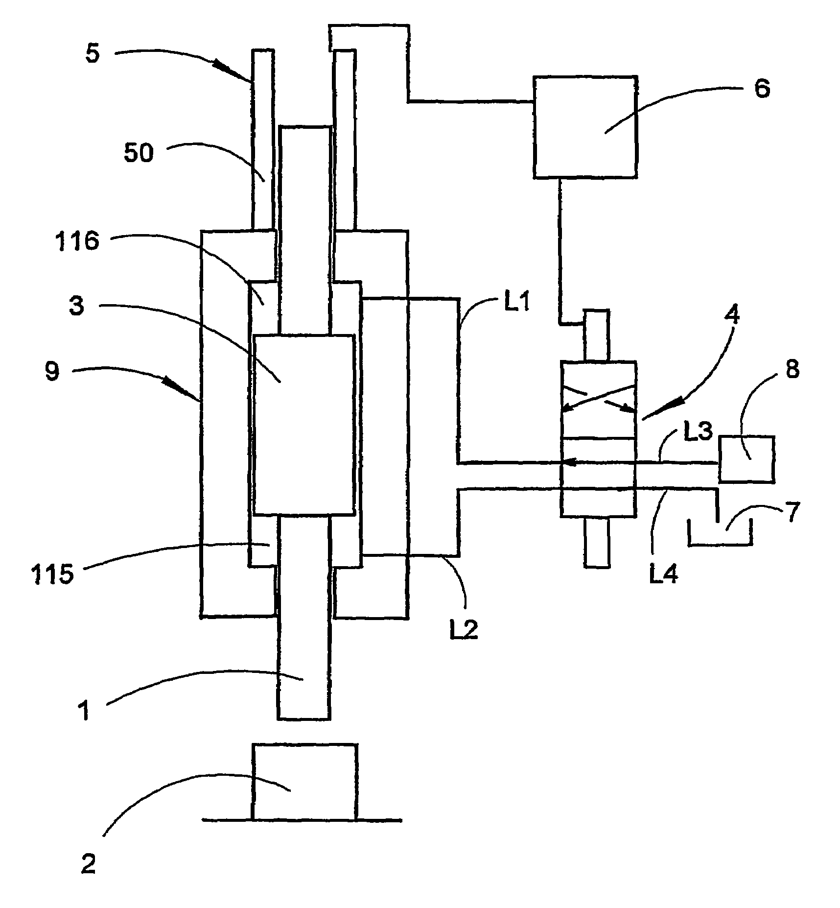
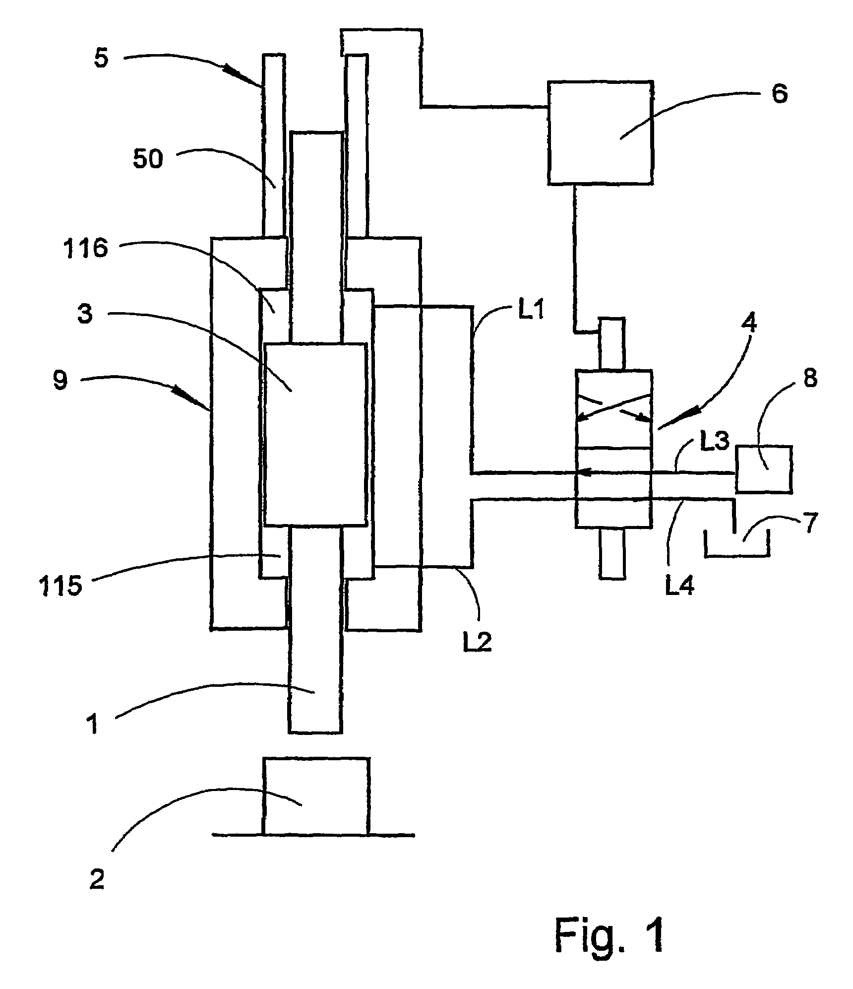
[0015]FIG. 1 shows a first preferred embodiment according to the invention. A hydraulic piston / cylinder unit 9 is shown, with a hydraulic piston 3 which is provided, at its lower end, with a stamp means 1. This stamp means 1 is intended to transfer high kinetic energy to a material body 2 (or tool) for high-speed working. The diagrammatic FIG. also shows that the piston / cylinder unit 9 is provided with a lower pressure: chamber 115 and an upper pressure chamber 116. The upper pressure chamber 116 is connected to a valve means 4 via a first line L1. The lower chamber 115 is connected to the same valve means 4 via a second line L2. On its other side, the valve means 4 is connected, via a third line L3, to a pressure source 8 and, via a fourth line L4, to a tank 7 (in most cases atmospheric pressure). In a first position (shown in FIG. 1), the valve means couples the pressure source 8 together with the first line L1 so that the upper chamber 116 is pressurized. At the same time, the lo...


PUM

PropertyMeasurementUnit
Forceaaaaaaaaaa
Pressureaaaaaaaaaa
Timeaaaaaaaaaa

Abstract

The present invention relates to a method for material working utilizing high kinetic energy, in which a stamp or striking body transfers, by delivering a blow, high kinetic energy to a material body that is to be worked, after which a rebound of the stamp occurs. In an embodiment of the method, a measure is taken in conjunction with said blow delivered, which measure prevents said stamp from delivering an afterblow with an appreciable kinetic energy content, for the purpose of avoiding negative effects as a consequence of afterblows.

Description

TECHNICAL FIELD[0001]The present invention relates to a method for material working utilizing high kinetic energy, comprising a non-oscillating stamp means which is driven from a starting position by an applied force for the purpose of by means of a single blow, transferring high kinetic energy to a material body which is to be worked, after which a rebound of the stamp means occurs after said blow. The invention also relates to a device for implementing the method.STATE OF THE ART[0002]In high-speed working, high kinetic energy is utilized for forming / working a material body. In connection with high-speed working, use is made of percussion pressing machines in which the pressing piston has a considerably higher kinetic energy than in conventional working; it often has a speed which is roughly 100 times higher or more than in conventional presses, in order to carry out cutting, punching and forming of metal components, powder compacting and similar operations. Within high-speed work...

Claims


Application Information

Patent Timeline
IPC IPC(8): B30B13/00E21B7/00B30B15/02B21J7/28B21J7/46B22F3/087B30B5/00B30B15/00B30B15/18
CPCB21J7/28B22F3/087B21J7/46
Inventor DAHLBERG, ANDERS
Owner CELL IMPACT
Why Eureka
Try Eureka