Polymer valves
a technology of polymer valves and valves, applied in the field of polymer valves, can solve the problems of valve function, valve closure, and disruption of heating
- Summary
- Abstract
- Description
- Claims
- Application Information
AI Technical Summary
Benefits of technology
Problems solved by technology
Method used
Image
Examples
example 1
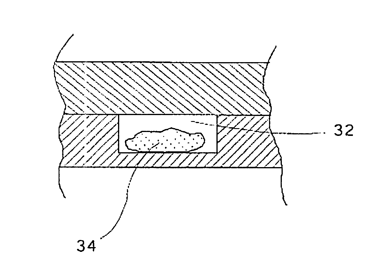
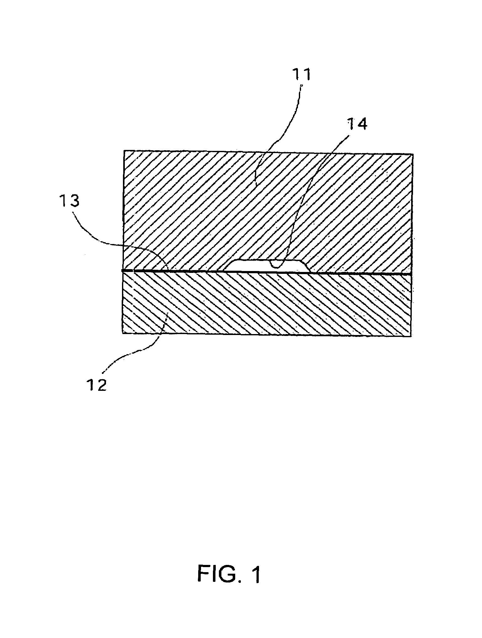
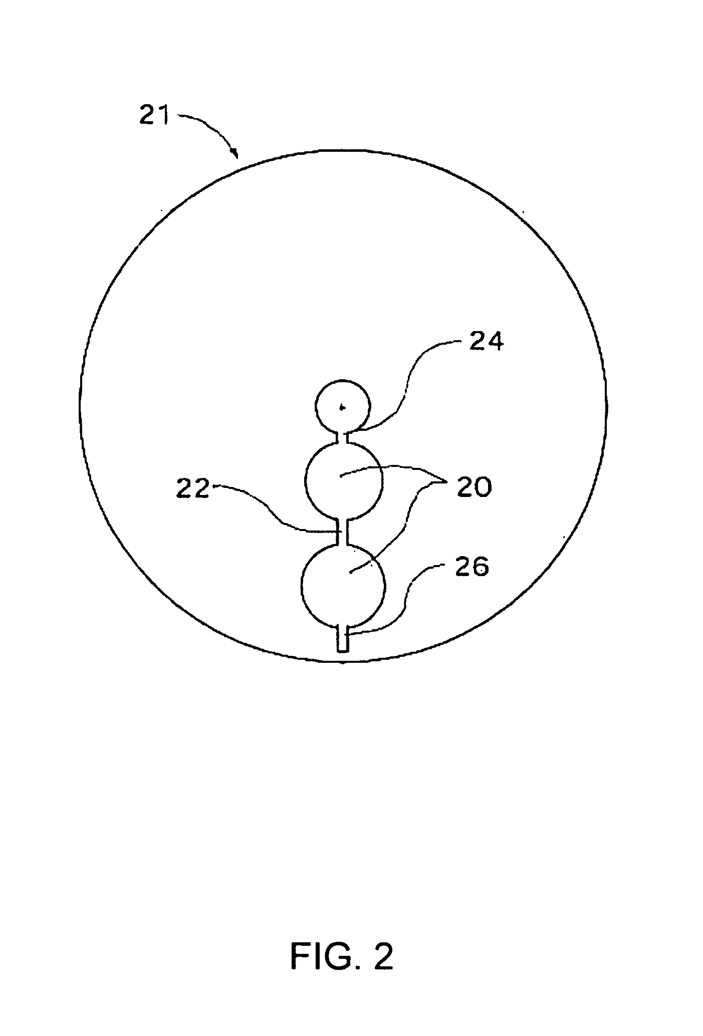
[0070]N-isopropylacrylamide (0.5 g) and N,N-methylene bisacrylamide (0.01 g) was dissolved in water (4.0 ml). 0,1 ml of a photo-initiator (Irgacure 184, Ciba-Geigy, 100 mM in ethylene glycol) was then diluted in 0.5 ml water, before mixing it with the monomer solution. A drop of the monomer solution was transferred to a channel in a microfabricated CD disc made of plastic (polycarbonate), and covered by a microscope glass cover slip. The monomer solution inside the channel was then illuminated with UV light through the glass cover slip for 10 minutes in order to polymerize the monomers.
[0071]When the polymerization was completed, a hydrostatic pressure using an aqueous dye solution was applied to the inlet of the channel. No liquid was seen to flow through the channel (see FIG. 5a). The CD disc was then left at 40° C. for 5 minutes, and a hydrostatic pressure was again applied to the channel. This time the liquid immediately flowed through the channel (see FIG. 5b). The CD disc was ...
example 2
[0072]A microscope cover glass was wiped with methacryloxytriethoxysilane and rinsed with water and ethanol. A gel-forming solution was prepared from 0.5 g N,N-diethylacrylamide, 10 mg N,N′-methylenebisacrylamide, 6.5 ml distilled water and 0.1 ml of a 0.1 M solution of Irgacure-184 in ethylene glycol. A droplet of this solution was placed in a channel of a polycarbonate CD disc having a recessed 100 μm deep channel pattern on its surface, and a microscope cover glass was placed over the droplet with the treated side facing downwards. The package was placed on a cold steel plate under an array of low pressure mercury lamps and illuminated for 5 min to polymerize the monomers. A transparent gel was formed in the channels, which turned opaque upon heating to 45° C., and again turned transparent when it was cooled below room temperature. An aqueous dye solution was able to penetrate the channel system at 45° C., thus proving that a free path-way for fluid flow was provided. At room tem...
example 3
[0073]A gel-forming solution was prepared from 0,5 g N,N-diethylacrylamide, 10 mg N,N′-methylenebisacrylamide, 6,5 ml distilled water and 0,1 ml of a 0,1 M solution of Irgacure-184 in ethylene glycol. A droplet of this solution was placed in a channel of a polycarbonate CD disc having a recessed 100 μm deep channel pattern on its surface, and a microscope cover glass was placed over the droplet. The package was placed on a cold steel plate under an array of low pressure mercury lamps and illuminated for 5 min to polymerize the monomers. A transparent gel was formed in the channels, which turned opaque upon heating to 45° C., and again turned transparent when it was cooled below room temperature. An aqueous dye solution was able to penetrate the channel system at 45° C., thus proving that a free path-way for fluid flow was provided. At room temperature the channel was blocked and no dye solution penetrated.
PUM
| Property | Measurement | Unit |
|---|---|---|
| depth | aaaaa | aaaaa |
| depth | aaaaa | aaaaa |
| distance | aaaaa | aaaaa |
Abstract
Description
Claims
Application Information
 - R&D
- Intellectual Property
- Life Sciences
- Materials
- Tech Scout
- Unparalleled Data Quality
- Higher Quality Content
- 60% Fewer Hallucinations
Browse by: Latest US Patents, China's latest patents, Technical Efficacy Thesaurus, Application Domain, Technology Topic, Popular Technical Reports.
© 2025 PatSnap. All rights reserved.Legal|Privacy policy|Modern Slavery Act Transparency Statement|Sitemap|About US| Contact US: help@patsnap.com


