
Electrical connector including silicone elastomeric material and associated methods

a technology of elastomeric material and electric connector, which is applied in the direction of coupling/support, coupling device connection, electrical apparatus, etc., can solve the problems of difficulty in manual pushing of electrical conductors, less accurate and reliable, and difficult fabrication of voltage test points, etc., to achieve the effect of being ready to manufactur

Inactive Publication Date: 2006-09-12
THOMAS & BETTS INT INC
View PDF61 Cites 53 Cited by
  • Summary
  • Abstract
  • Description
  • Claims
  • Application Information

AI Technical Summary

Benefits of technology

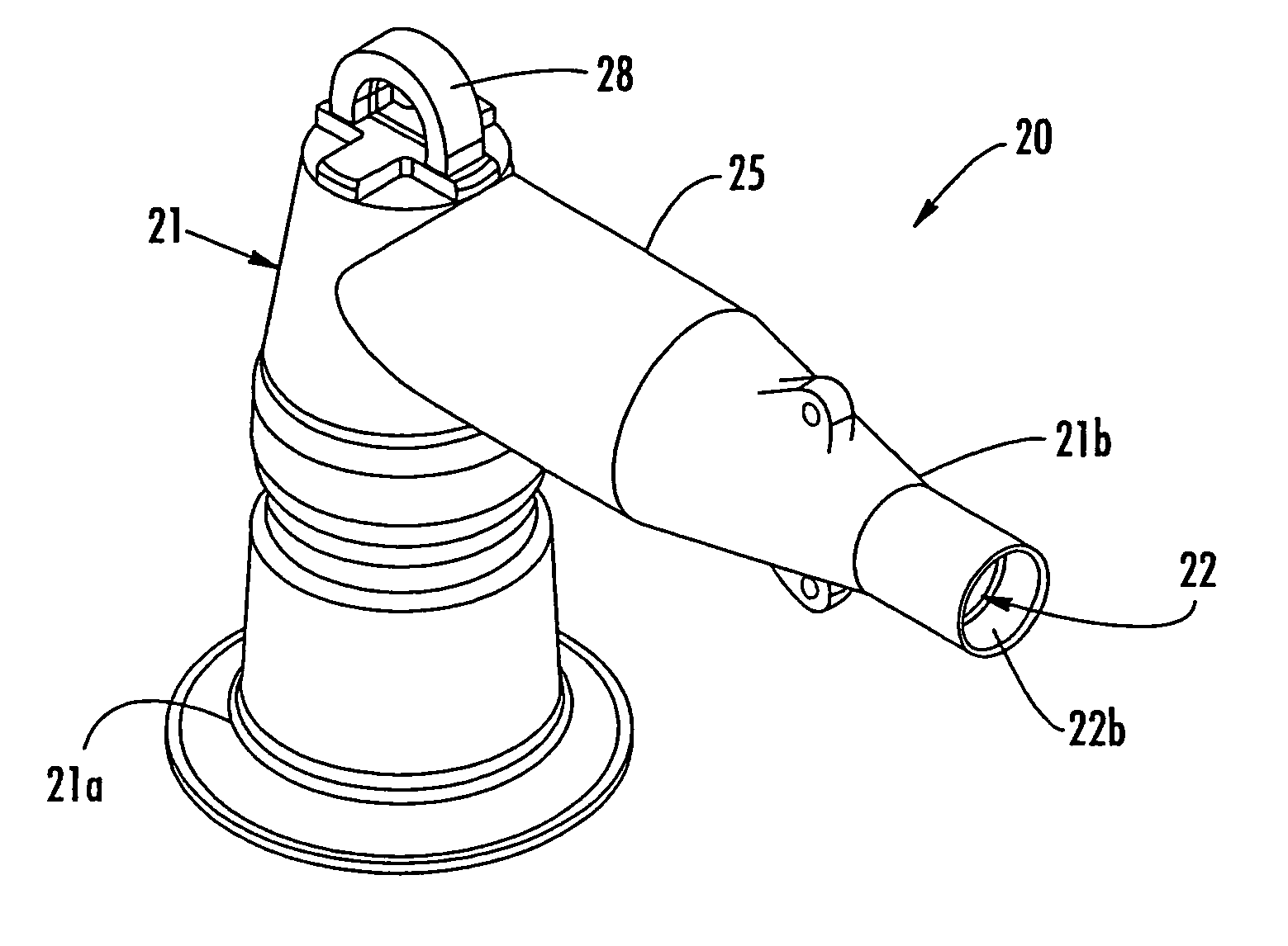
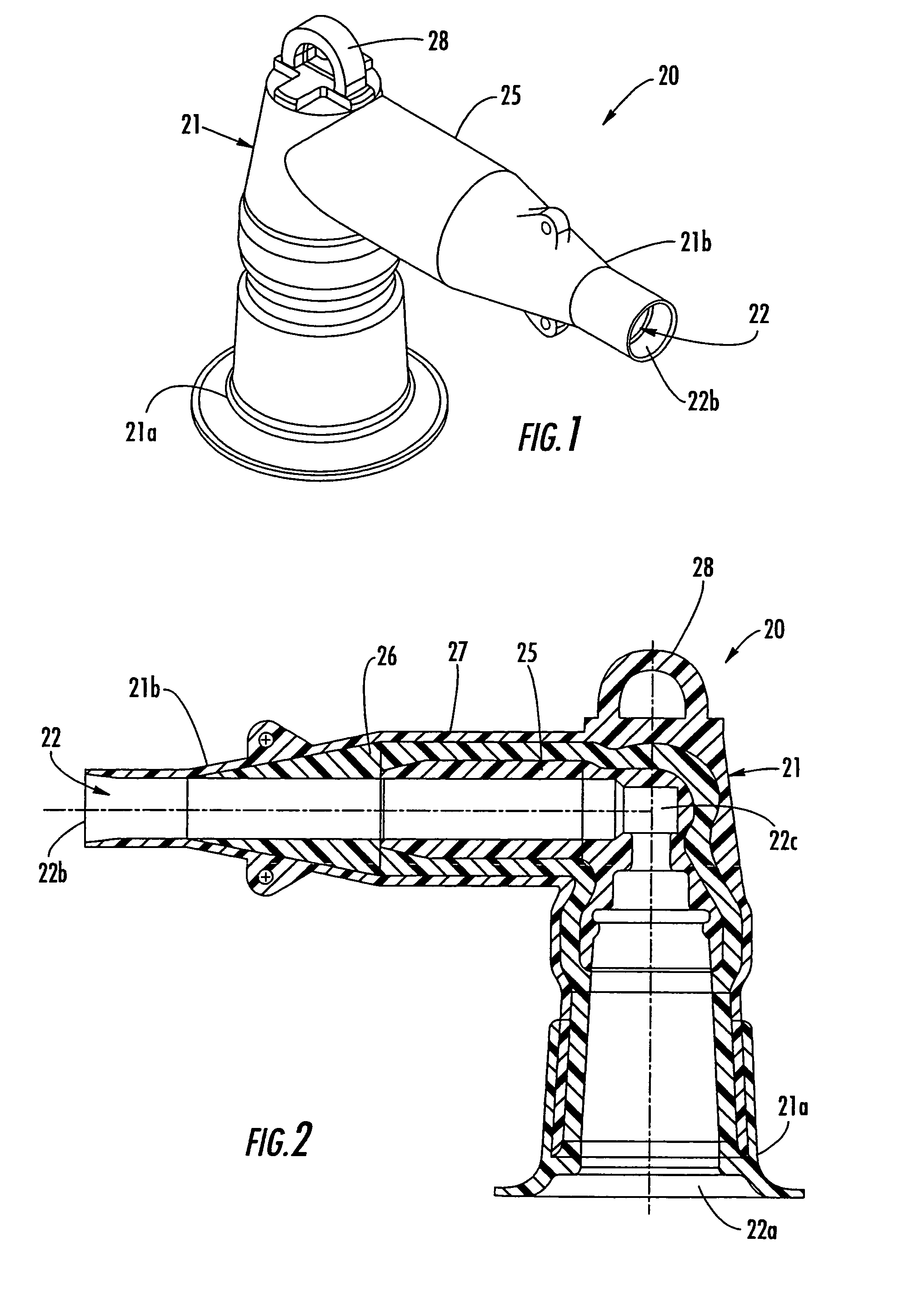
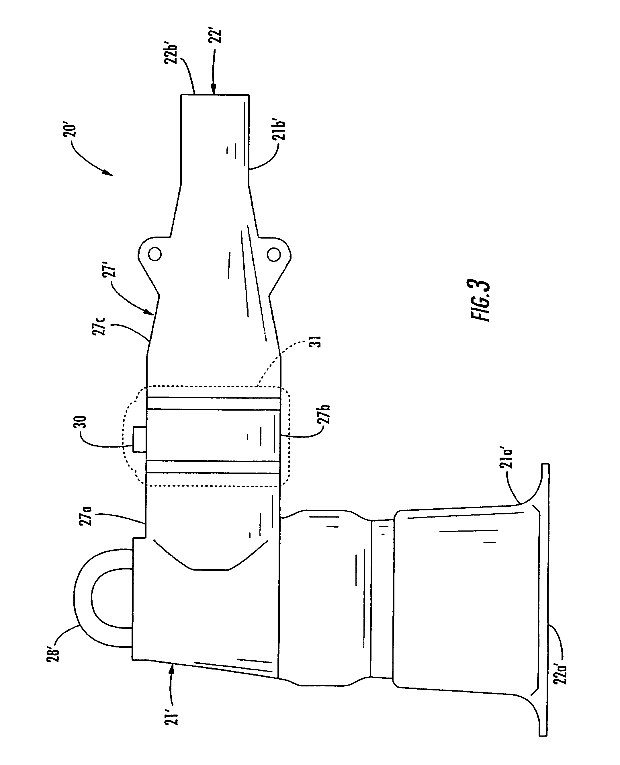
"The invention is an electrical connector that is useful for high voltage applications and can be easily manufactured. The connector has a unique design with layers of silicone elastomeric material that provide excellent electrical performance and can handle high levels of stress. The connector also includes a cold shrink core and a monitor point for voltage monitoring. The method for making the connector involves overmolding the layers of silicone elastomeric material and shaping the outer end of the passageway to prevent flashover. Overall, the invention provides an improved electrical connector that is reliable and efficient."

Problems solved by technology

Such voltage test points may be somewhat difficult to fabricate, and upon contamination and repeated use, they may become less accurate and less reliable.
Accordingly, another potential shortcoming of such an elbow connector is the difficulty in manually pushing the electrical conductor into the second end of the connector body.
However, this connector may suffer from the noted drawbacks in terms of manufacturing speed and cost.
Unfortunately, this approach may also be relatively slow and cumbersome.
Another issue that may arise for an elbow connector is electrical stress that may damage the first or semiconductive layer.

Method used


Image

  • Electrical connector including silicone elastomeric material and associated methods
  • Electrical connector including silicone elastomeric material and associated methods
  • Electrical connector including silicone elastomeric material and associated methods

Examples


second embodiment

[0056]a first layer 40′ is explained with particular reference to FIG. 6. In this embodiment, the first layer 40′ includes slightly differently shaped first and second ends 41′, 42′. In addition, only a single rib 44′ is provided at the right angle portion of the bend to reduce electrical stress thereat. The configuration of the ribs 44 or single rib 44′, as well as the configuration of the other connector body portions will be dependent on the desired operating voltage and current, as will be appreciated by those skilled in the art.

[0057]Of course, these stress control techniques can be used with any of the different electrical connector embodiments described herein. Typical 200 and 600 Amp elbow connectors, for example, may benefit from such stress control techniques as will be appreciated by those skilled in the art.

[0058]Referring now additionally to FIGS. 7–10 an anti-flashover feature of an elbow connector 50 is now described. A conventional elbow connector is subject to poten...


PUM


Abstract

An electrical connector may include a connector body having a passageway therethrough. The connector body may include a first layer adjacent the passageway, a second layer surrounding the first layer and comprising an insulative silicone elastomeric material, and a third layer surrounding the second layer. The third layer preferably has a relatively low resistivity, and may also include a semiconductive silicone elastomeric material. In some embodiments, the first layer may also include a semiconductive silicone elastomeric material. The silicone elastomeric material layers may be overmolded to thereby increase production speed and efficiency thereby lowering production costs. The silicone elastomeric material may also provide excellent electrical performance and other advantages.

Description

RELATED APPLICATION[0001]This application is a continuation-in-part application of U.S. patent application Ser. No. 10 / 438,750 filed May 15, 2003 now U.S. Pat. No. 6,905,356, that, in turn, is based upon prior filed provisional application Ser. No. 60 / 380,914 filed May 16, 2002, the entire subject matter of each being incorporated herein by reference.FIELD OF THE INVENTION[0002]The present invention relates to electrical products, and more particularly, to electrical connectors for electrical systems and associated methods.BACKGROUND OF THE INVENTION[0003]An electrical distribution system typically includes distribution lines or feeders that extend out from a substation transformer. The substation transformer is typically connected to a generator via electrical transmission lines.[0004]Along the path of a feeder, one or more distribution transformers may be provided to further step down the distribution voltage for a commercial or residential customer. The distribution voltage range...

Claims


Application Information

Patent Timeline
Patent Type & Authority Patents(United States)
IPC IPC(8): H01R13/53H01R13/504H01R13/52
CPCH01R13/53H01R13/5205H01R13/504Y10S439/921
Inventor JAZOWSKI, ROY E.CAWOOD, MATTHEW D.
Owner THOMAS & BETTS INT INC
Learn More