Diffraction grating-based encoded particle

a technology of encoded particles and diffraction grating, applied in the field of optical identification, can solve the problems of insufficient bar codes, insufficient different codes, and inability to withstand harsh temperature, chemical, nuclear and/or electromagnetic environments, and achieve the effect of making very small

Inactive Publication Date: 2006-09-12
ILLUMINA INC
View PDF212 Cites 85 Cited by
  • Summary
  • Abstract
  • Description
  • Claims
  • Application Information

AI Technical Summary

Benefits of technology

[0006]Objects of the present invention include provision of an optical identification element or platform that allows for a large number of distinct codes, can be made very small, and / or can withstand harsh environments.

Problems solved by technology

Existing technologies, such as bar codes, electronic microchips / transponders, radio-frequency identification (RFID), and fluorescence and other optical techniques, are often inadequate.
For example, existing technologies may be too large for certain applications, may not provide enough different codes, or cannot withstand harsh temperature, chemical, nuclear and / or electromagnetic environments.

Method used


Image

  • Diffraction grating-based encoded particle
  • Diffraction grating-based encoded particle
  • Diffraction grating-based encoded particle

Examples


Embodiment Construction

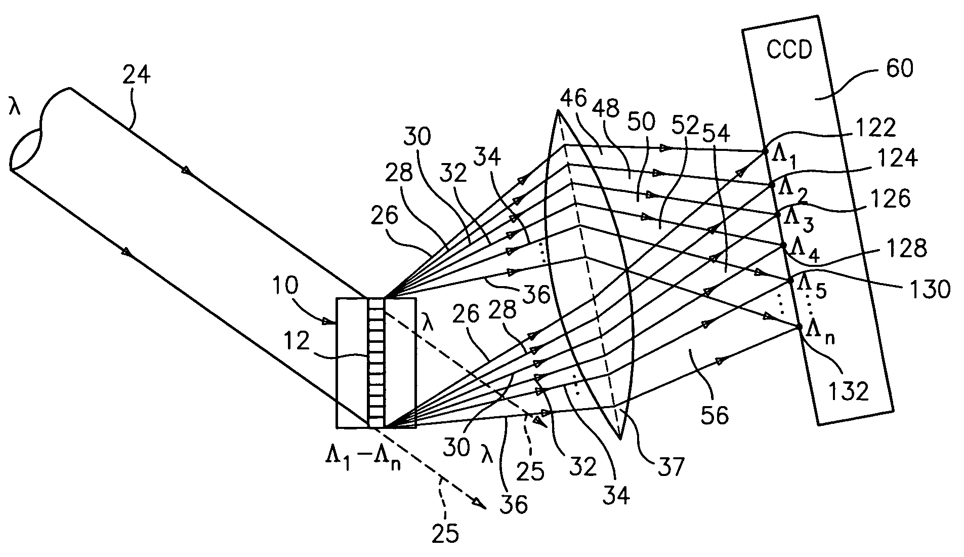
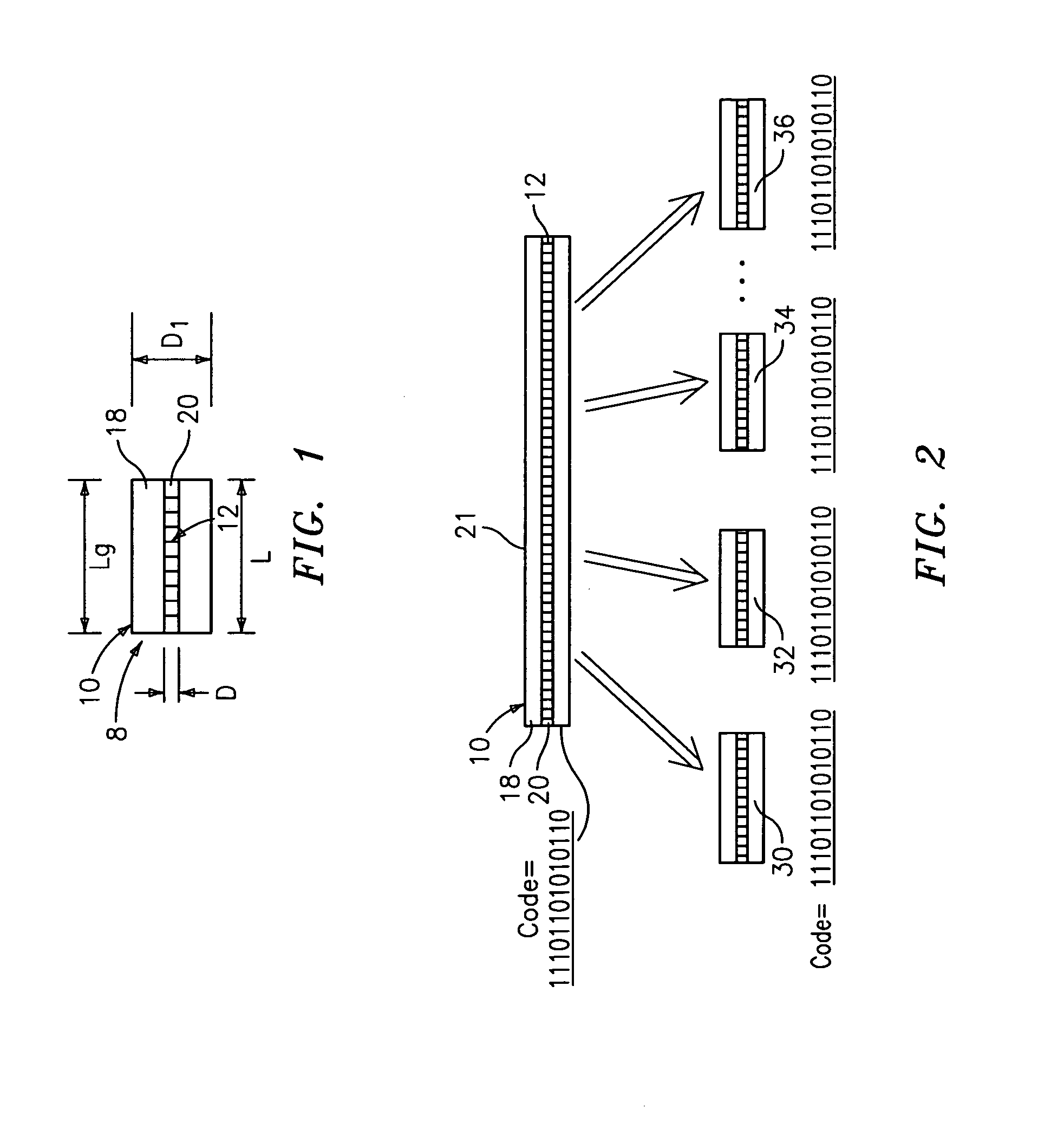
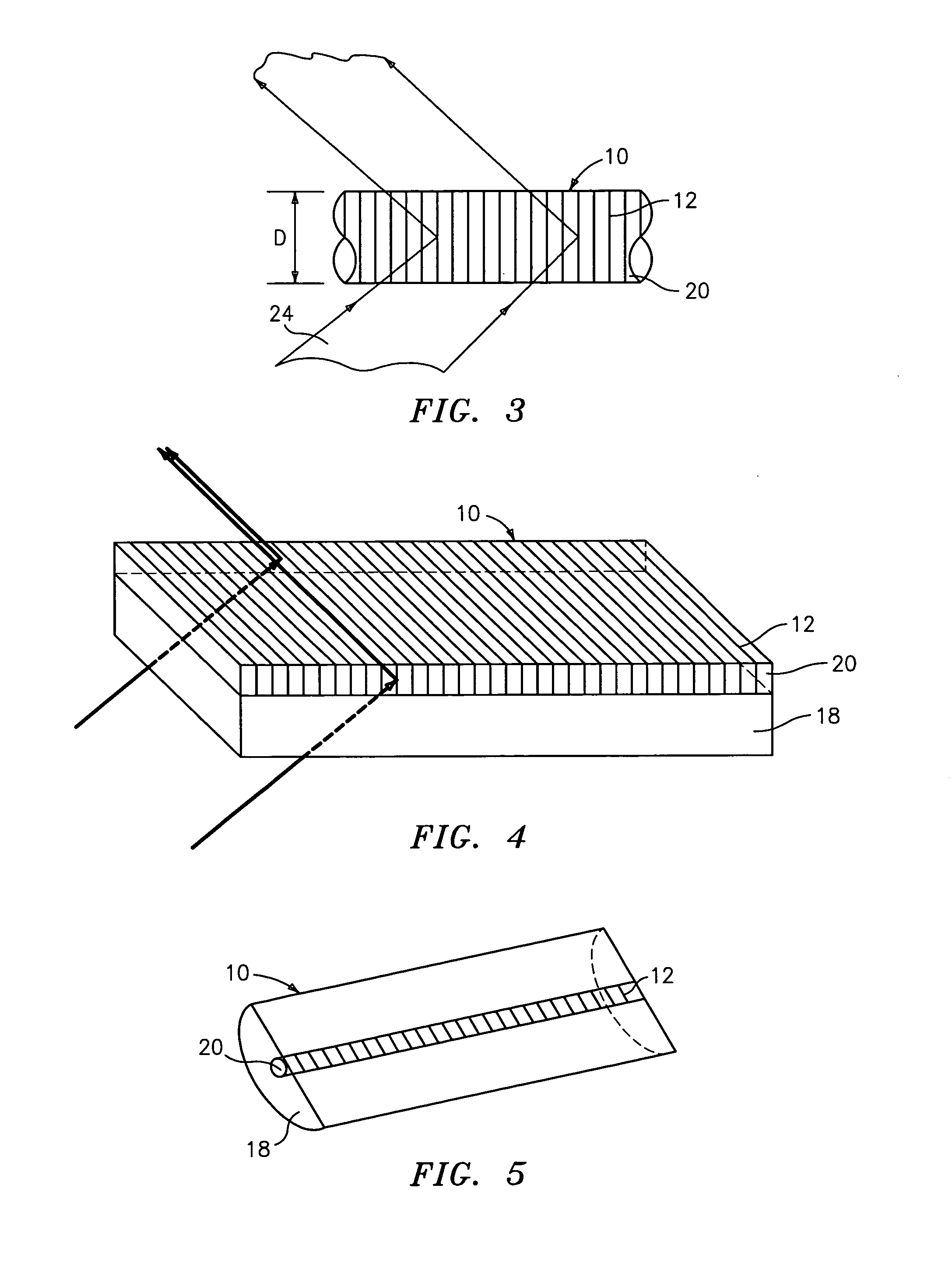
[0057]Referring to FIG. 1, an optical identification element 8 comprises a known optical substrate 10, having an optical diffraction grating 12 disposed (or written, impressed, embedded, imprinted, etched, grown, deposited or otherwise formed) in the volume of or on a surface of a substrate 10. The grating 12 is a periodic or a periodic variation in the effective refractive index and / or effective optical absorption of at least a portion of the substrate 10.

[0058]The substrate 10 has an inner region 20 where the grating 12 is located. The inner region may be photosensitive to allow the writing or impressing of the grating 12. The substrate 10 has an outer region 18 which does not have the grating 12 therein.

[0059]The grating 12 is a combination of one or more individual spatial periodic sinusoidal variations in the refractive index that are collocated along the length of the grating region 20 of the substrate 10, each having a spatial period (or pitch) Λ. The grating 12 (or a combina...


PUM

PropertyMeasurementUnit
lengthaaaaaaaaaa
lengthaaaaaaaaaa
lengthaaaaaaaaaa

Abstract

An encoded particle 8 includes a particle substrate 10; at least a portion of the substrate having at least one diffraction grating disposed therein, the grating having a resultant refractive index variation at a grating location, the grating being embedded within a substantially single material of the substrate; and the grating providing an output optical signal indicative of a code when illuminated by an incident light signal propagating in free space, the output optical signal being a result of passive, non-resonant scattering from the grating when illuminated by the incident light signal.

Description

CROSS REFERENCES TO RELATED APPLICATIONS[0001]This application claims the benefit of U.S. Provisional Patent Applications, Ser. No. 60 / 410,541, filed Sept. 12, 2002, and is a continuation-in-part of U.S. patent applications, Ser. No. 10 / 645,689 filed Aug. 20, 2003, each of which are incorporated herein by reference in their entirety.[0002]U.S. patent application Ser. No. 10 / 661,082 (publication no. US 2004-0179267 A1), filed concurrently herewith, entitled “Method and Apparatus for Labeling Using Diffraction Grating-Based Encoded Optical Identification Element”, filed contemporaneously herewith, contains subject matter related to that disclosed herein, which is incorporated by reference in its entirety.TECHNICAL FIELD[0003]This invention relates to optical identification, and more particularly to optical elements used for identification or coding using diffraction gratings.BACKGROUND ART[0004]Many industries have a need for uniquely identifiable objects or for the ability to uniquel...

Claims


Application Information

Patent Timeline
Patent Type & Authority Patents(United States)
IPC IPC(8): G02B5/18G01N21/64G02B6/34G02B27/44G03H1/00G06K19/00G06K19/06G06T5/00G07D7/00G07D7/12
CPCG06K7/1094G07D7/004G07D7/0013G06K19/06009B01J2219/005B01J2219/0056G06K2019/06234G06K2019/0629G07D7/0032
Inventor MOON, JOHN A.PUTNAM, MARTIN A.
Owner ILLUMINA INC
Why Eureka
Try Eureka