
Intermediate transfer member for carrying intermediate electrophotographic image

a transfer member and electrophotographic technology, applied in the field of image transfer members, can solve the problems of inability to achieve bias voltage, poor conformability of tedlar®, and current flow through the transfer nip, and achieve the effect of increasing the transfer efficiency

Inactive Publication Date: 2006-09-12
S PRINTING SOLUTION CO LTD
View PDF21 Cites 5 Cited by
  • Summary
  • Abstract
  • Description
  • Claims
  • Application Information

AI Technical Summary

Benefits of technology

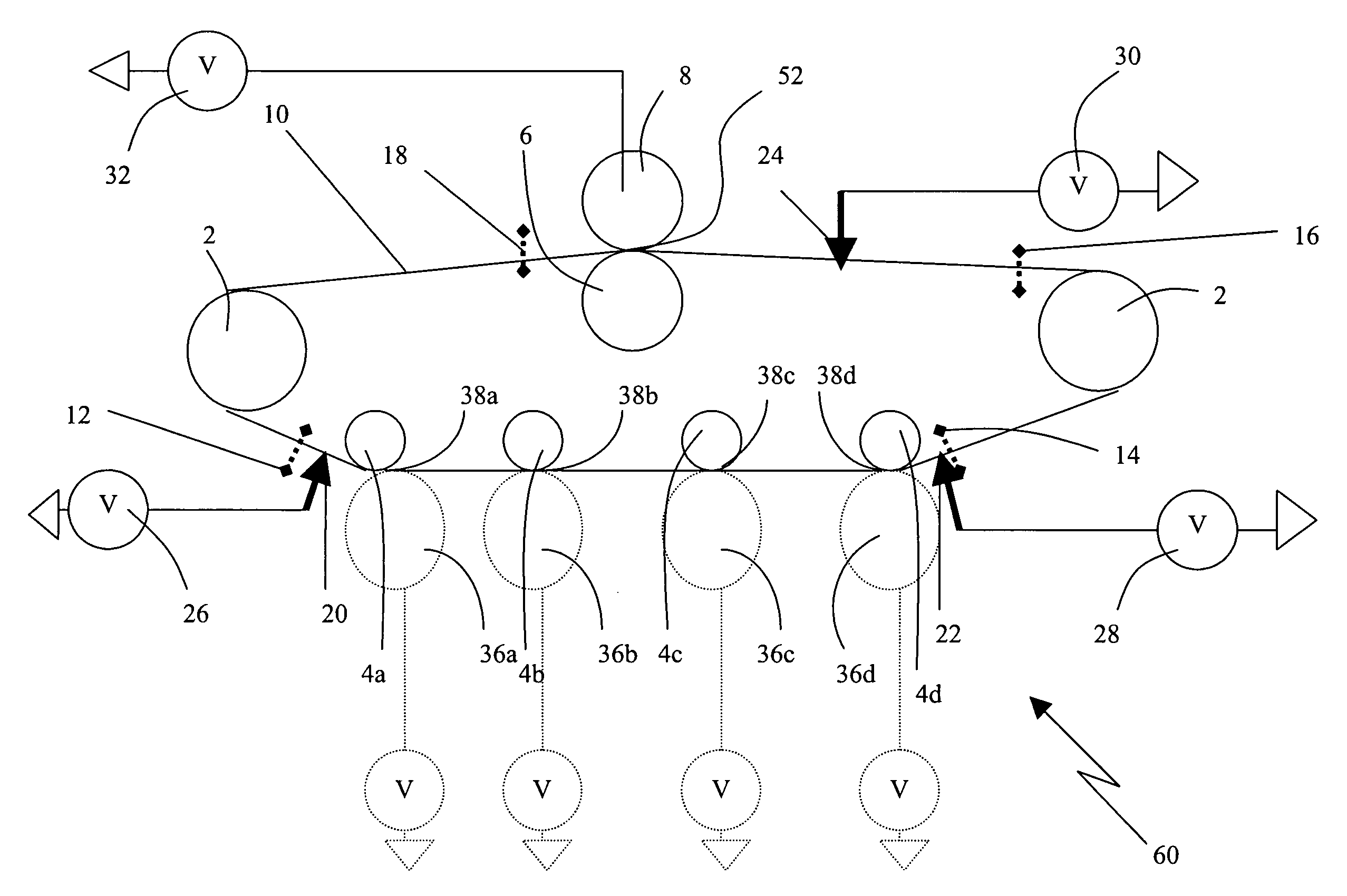
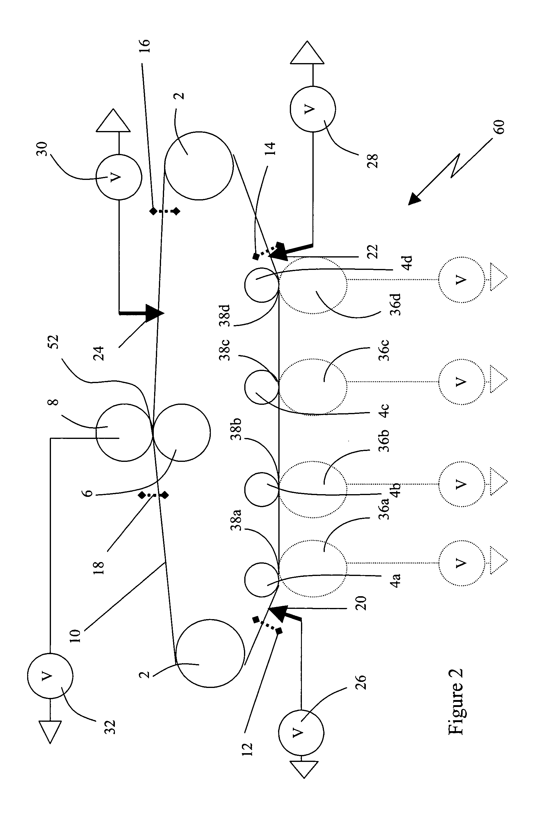
"This patent describes an improved image transfer belt (ITB) for use in electrophotographic processes. The ITB is segmented into electrically isolated regions that allow different voltages to be placed at different locations along the same ITB for different steps and / or different qualitative results in the process. This optimization of voltages and increases transfer efficiency. The patent also describes an intermediate transfer member with a non-conductive layer, a conductive layer, and a resistive layer, which can be charged by applying a voltage to the conductive layer. The resistive layer has separation elements between segments to improve transfer efficiency. The method of using the ITB involves exposing and developing an image on an image receiving member and then transferring it to the ITB with a different voltage to achieve optimal transfer efficiency. The technical effects of this invention include improved image quality, higher transfer efficiency, and better control over the voltage and current during the printing process."

Problems solved by technology

Tedlar® suffers from poor conformability.
If the ITB is too electrically conductive, current will flow through the transfer nip and a bias voltage will not be possible.
In the prior art, belts that were made thicker to increase ITB durability and longevity suffered adverse effects on electric field strength.
Contamination of the ITB back up rollers can result from paper lint and / or stray toner and can cause poor roller-to-ITB contact, which reduces the strength of the electric field.
This can result in inconsistent toner transfer across the ITB surface.
In both cases, complex and difficult manufacturing processes must be employed to produce a functional ITB that meets the requirements specified above.
This process requires significant time and highly specialized equipment.
This is a slow manufacturing process producing only a single ITB at a time.
This increases the complexity of the electrical circuitry in a printer and brings about uncertainty of electrical continuity between the conductive backup roller and the ITB especially when unwanted stray paper lint and toner contaminate this backup roller / ITB contact point.
Also the cured polymers and elastomers by themselves are too electrically resistive at an ITB thickness that provides acceptable durability resulting in a weak electric field and poor toner transfer efficiency.
A paste-like consistency can result, making application to the mandrel or cylinder difficult unless the viscosity of the paste-like dispersion is reduced by heating.
Solvents which could be added to reduce the viscosity of the dispersion cannot be used because the application thickness required for ITB durability is large enough to cause solvent trapping during the curing process and subsequent blistering which reduces ITB yield.
These manufacturing processes are also labor intensive with a low ITB manufacturing output rate.
All of these factors result in a high ITB cost.
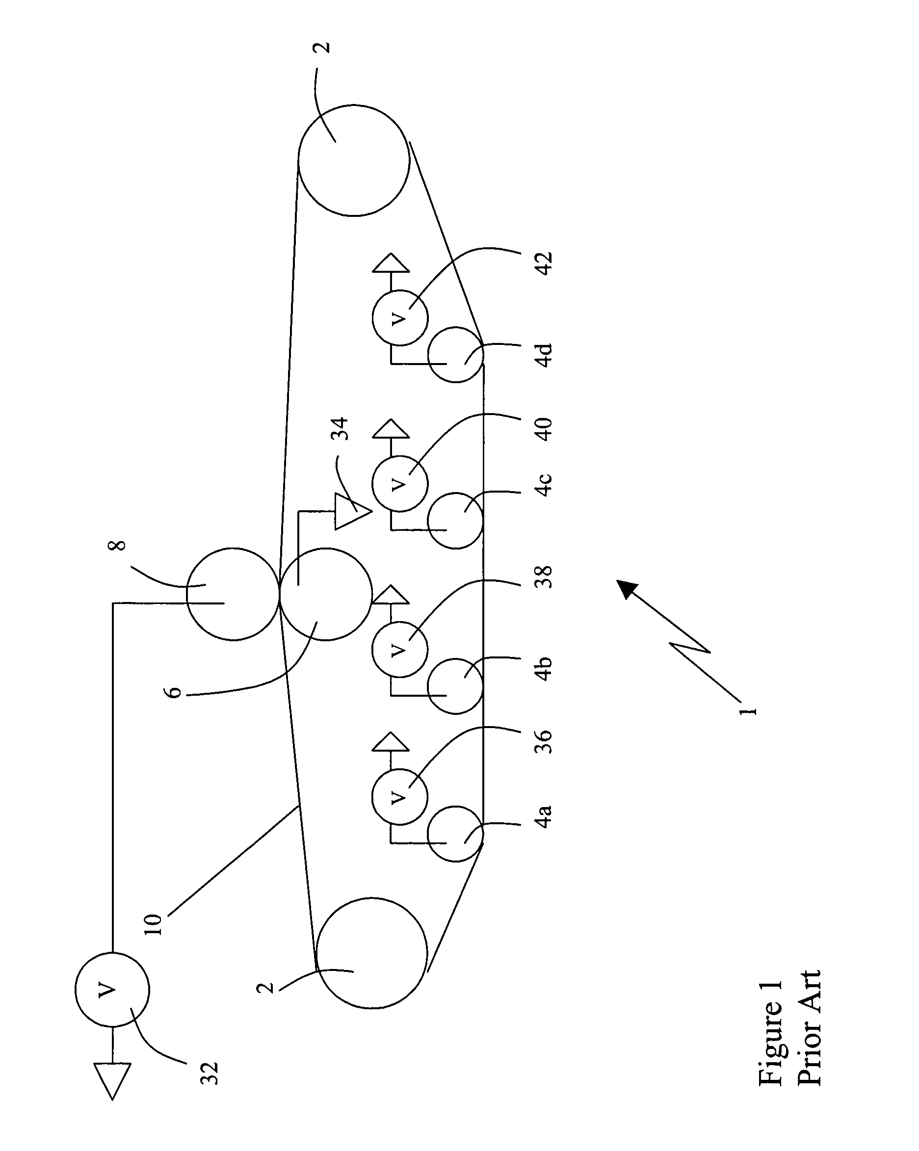
While many of the prior art rubber belts are resistive enough to be able to apply independent voltages at each transfer station, toner transfer efficiency is reduced due to the high resistivity and poor roll-to-belt contact.

Method used


Image

  • Intermediate transfer member for carrying intermediate electrophotographic image
  • Intermediate transfer member for carrying intermediate electrophotographic image
  • Intermediate transfer member for carrying intermediate electrophotographic image

Examples


example

[0058]A fluorosilicone prepolymer from General Electric Co. with the designation FRV1106 was coated onto Al / Pet and then made into an ITB. This was accomplished by first preparing a 40% solution of FRV1106 in MEK. 398.4 grams of FRV1106 and 1.6 grams of tetrabutyl titanate (TBT) catalyst from Du Pont were added to 600 grams of MEK in a glass jar. The jar was tightly capped and the FRV1106 brought into solution by putting the jar on an oscillating shaker for 4 hours.

[0059]A roll to roll coater with an extrusion type coating bar was used to apply the FRV1106 solution to the Al / PET web. The coating bar has a narrow extrusion slot oriented perpendicular to the web and is positioned so that liquids and solutions can be applied to the Al / PET web as a thin liquid coating as the Al / PET web is pulled past the extrusion slot. A positive displacement pump and associated plumbing is used to meter the coating liquid through the extrusion bar slot and onto the moving web. The size of the positive...


PUM


Abstract

An electrophotographic imaging apparatus having a first toner accepting layer and an intermediate transfer member. The first toner accepting layer is positioned in electrical contact with a) a charge provider, b) an irradiation source that activates photoconductivity in the first toner accepting layer, and b) at least one toner applicator, so that a first toner image can be formed on the first toner accepting layer. The first toner layer is movable, after interaction with a), b) and c), into contact with the intermediate transfer layer from which the first toner image can be transferred to an image bearing member. The intermediate transfer member comprises a non-conductive flexible film layer, a layer of an electrically conductive material affixed to a first surface of the non-conductive flexible film layer and segmented into electrically isolated regions or zones, and the electrically conductive material layer has an electrically resistive polymeric coating thereon.

Description

RELATED U.S. APPLICATION DATA[0001]This Application claims priority from U.S. Provisional Patent Application No. 60 / 429,713 filed on Nov. 29, 2002.BACKGROUND OF THE INVENTION[0002]1. Field of the Invention[0003]This invention relates to an image transfer member for use in electrophotographic printing in which the image transfer member is used to transport an intermediate image between the photoconductive drum and the final image receiving media.[0004]2. Background of the Invention[0005]In the electrophotographic printing process, a toner image is formed on a photoconductive drum using electrostatic techniques that are well known in the art. For example, an organic photoreceptor in the form of a plate, belt, disk, sheet, or drum having an electrically insulating photoconductive element on an electrically conductive substrate is imaged by first uniformly electrostatically charging the surface of the photoconductive element, and then exposing the charged surface to a pattern of light. ...

Claims


Application Information

Patent Timeline
Patent Type & Authority Patents(United States)
IPC IPC(8): G03G15/01G03G13/20G03G15/16
CPCG03G15/1645G03G15/1685G03G15/162G03G2215/1623G03G2215/0119G03G15/16
Inventor STULC, LEONARDKELLIE, TRUMAN FRANK
Owner S PRINTING SOLUTION CO LTD
Learn More