Method and apparatus for decoding received data in a communications system

a communication system and received data technology, applied in the direction of coding, code conversion, electrical apparatus, etc., can solve the problems of reducing transmission efficiency, increasing the number of structure bits, and worse reception, and achieve high stability and reliability

Inactive Publication Date: 2006-09-12
SOCIONEXT INC
View PDF4 Cites 16 Cited by
  • Summary
  • Abstract
  • Description
  • Claims
  • Application Information

AI Technical Summary

Benefits of technology

[0049]It is an object of the invention to initialize path metric in a Viterbi decoder according to strength of a noise on a transmission line and coding rates of continuous data streams so as to optimally decode a plurality of data stream, which are multiplexed without inserting an “end bit” thereinto, with high stability and reliability.

Problems solved by technology

When the weather is bad the reception becomes worse.
Meanwhile, such data stream with high redundancy has a disadvantage that a number of structure bits increases and transmission efficiency is lowered.
Furthermore, this method simultaneously reduces the error correction ability.
However, as the transmission efficiency becomes higher, adjacent transmission symbols are closer to each other so that clear distinction between the phases becomes difficult.
As a result, error can be easily generated in the information.
For example, consider a case in which two or more kinds of coding rates are used between the data streams composing the multiplexed data stream, and comparatively big noise is mixed on the transmission line.
In this case, although error can be sufficiently corrected in the data stream having coding rate of high error correction ability in the multiplexed data streams, error is still included in a decoded result of the data stream having coding rate of low error correction ability.
For this reason, the data stream having coding rate of high error correction ability cannot be decoded correctly.
However, the “information receiver” cannot solve the above problem when the “end bit” cannot be inserted into the data streams from the viewpoint of the standard of data transmission in digital satellite broadcasting or the like.
If the “end bit” is not inserted and not detected and the path metric is initialized at a change point of the coding rate, namely, a point that transmission of next data stream is started, there arises a new problem that a convolutional code fails and the error correction ability is lowered.
As a result, more errors occur than the case that the initialization is not executed.

Method used


Image

  • Method and apparatus for decoding received data in a communications system
  • Method and apparatus for decoding received data in a communications system
  • Method and apparatus for decoding received data in a communications system

Examples


first embodiment

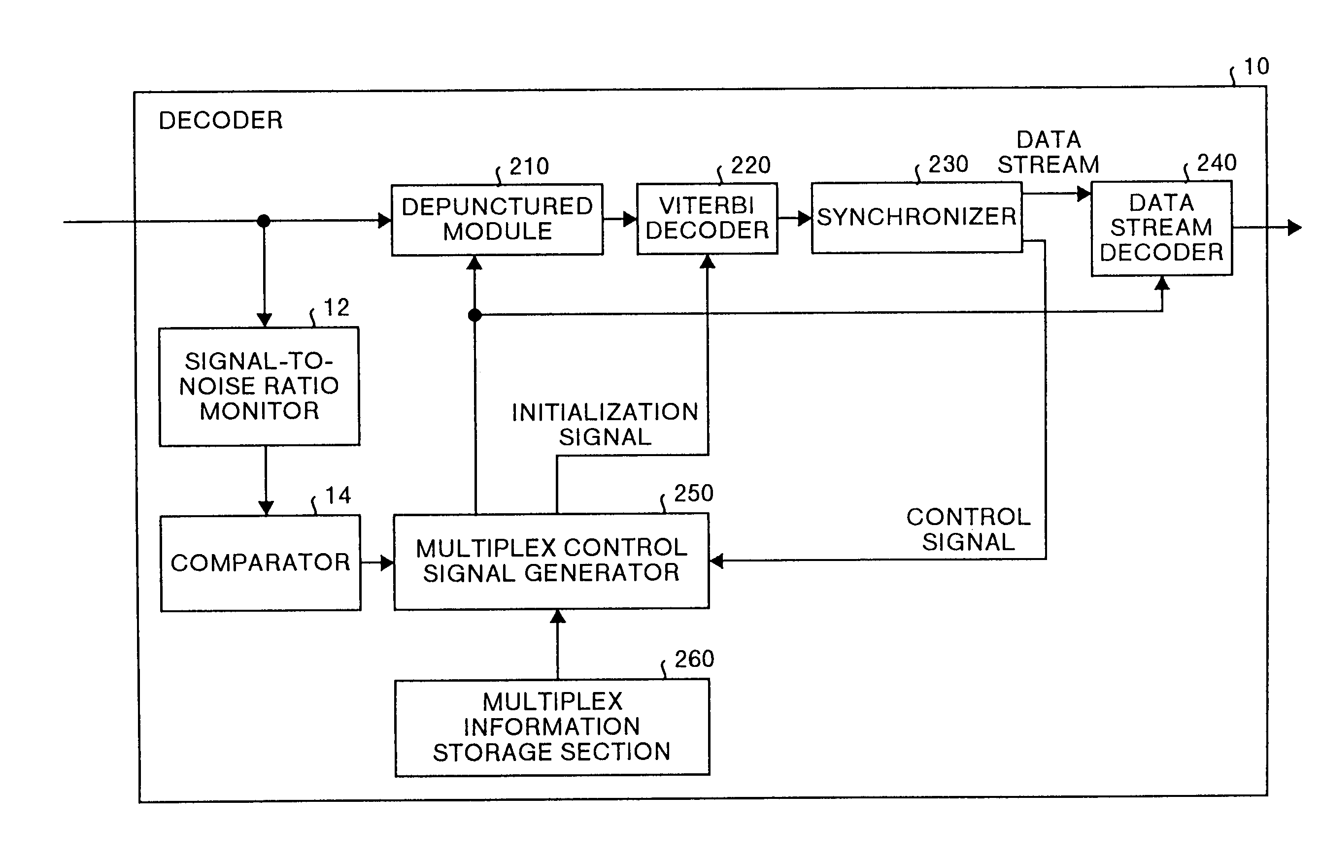
[0069]FIG. 7 is a block diagram showing a schematic structure of the decoder according to the The decoder 10 shown in FIG. 7 is provided with a signal-to-noise ratio monitor 12 and a comparator 14. The signal-to-noise ratio monitor 12 measures strength of noise from a signal input into the depuncture module 210 so as to digitize the measured noise strength. The comparator 14 compares the output of the signal-to-noise ratio monitor 12 with a predetermined value and outputs a signal representing the result of comparison (hereinafter, referred to as a post signal). The multiplex control signal generator 250 outputs an initialization signal to the Viterbi decoder 220 based on the post signal received from the comparator 14. This process is different from the one executed in the conventional decoder 200.

[0070]The legends same as in FIG. 5 are provided to the other components which are common to those of the conventional decoder 200, and the explanation thereof is omitted. The Viterbi de...

second embodiment

[0088]The decoding method and the decoder initialize the Viterbi decoder 220 in the transmission system which transmits and receives data composed of multiplexed data stream at the point that the strength of noise mixed in the received signal exceeds the predetermined value and the data stream having coding rate of low error correction ability is changed into the data stream having coding rate of high error correction ability. As a result, the coded result with high reliability which is not much influenced by the noise can be obtained.

[0089]A decoding method and a decoder according to a third embodiment will be now explained. The decoding method and the decoder according to the third embodiment have the following characteristic in addition to the characteristic of the decoder 30 according to the second embodiment. Precisely, a plurality of multiplexed data stream are extracted from the data stream decoded by the data stream decoder 240 so as to be distributed.

[0090]FIG. 10 is a blo...

third embodiment

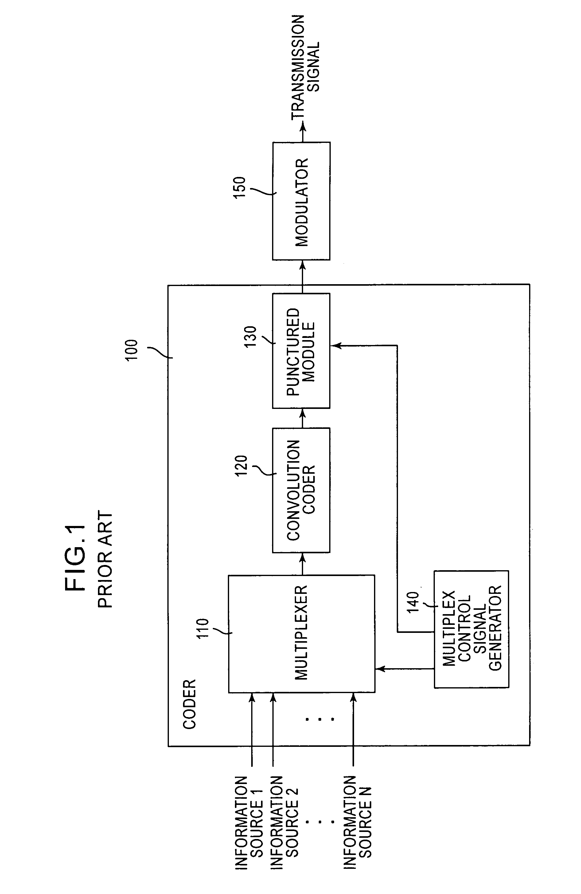
[0097]Operations of the decoder 60 which are different from those in the third embodiment will only be explained here. A plurality of information source data are coded by a system composed of the Reed-Solomon coding circuit, the frame structure circuit, the energy dispersion circuit and the interleaver in the multiplexer 110 of the coder 100. Moreover, the multiplex information is coded by the Reed-Solomon coding circuit and the energy dispersion circuit, and a synchronous code is added to the information source data and the multiplex information and they are multiplex. As a result, the data stream output from the coder of the transmitter is obtained.

[0098]The synchronizer 62, in the same manner as shown in FIG. 6, generates a control signal to be input into the multiplex control signal generator 250. Moreover, the synchronizer 62 extracts the data stream and the data stream representing the multiplex information from the input signal.

[0099]The data stream extracted in the synchroni...


PUM


Abstract

A plurality of data streams, which are coded by a convolution code and where coding rates and modulation systems are set respectively, and multiplexed in time division so that multiplex data are composed. A signal-to-noise ratio monitor measures the strength of the noise included in the multiplex data. A comparator outputs a post signal when a comparison indicates that the measured noise strength is equal to greater than a preset value. A multiplex control signal generator inputs an initialization signal into a Viterbi decoder at a timing at which decoding of individual data streams is started based on the received post signal. The Viterbi decoder initializes the calculated path metric upon receipt of the initialization signal.

Description

FIELD OF THE INVENTION[0001]The present invention relates to a technology of demodulating a received digital-modulated signal and decoding actual data from digital data obtained by the demodulation. More particularly, the invention relates to a decoding method, a decoder, a data receiving system, and a data transmission and receiving system which decodes a data stream, which is coded by using a convolutional code and is multiplexed in time division, using Viterbi decoding.BACKGROUND OF THE INVENTION[0002]Recently, as integrated circuits and coding techniques, which can process digital data at a high speed, are becoming available. Therefore, analog-system techniques are now replaced by such digital techniques. Particularly, growth television broadcasting service, satellite broadcasting service and the like are being converted to digital broadcasting.[0003]The digital satellite broadcasting adopts a radio communication system in which a carrier signal is transmitted via an artificial ...

Claims


Application Information

Patent Timeline
IPC IPC(8): H03M13/03H03M13/41
CPCH03M13/4161
Inventor YAMAUCHI, KEN
Owner SOCIONEXT INC
Why Eureka
Try Eureka