Internal riser inspection system, apparatus and methods of using same

a riser and inspection system technology, applied in the direction of surveying, wellbore/well accessories, instruments, etc., can solve the problems of affecting the inspection effect of the riser, and exposing the divers to extreme environmental conditions, so as to improve the acquisition of the orientation of the particles

Inactive Publication Date: 2006-09-19
HYDRIL USA DISTRIBUTION LLC
View PDF20 Cites 12 Cited by
  • Summary
  • Abstract
  • Description
  • Claims
  • Application Information

AI Technical Summary

Benefits of technology

[0016]In an embodiment of the present invention where a magnetic field is provided from outside the pipe, prior to performing the visual inspection, the operator applies a plurality of wire wraps around the outer diameter of the inspection area. After application of the MPI medium, the operator can energize the wire wraps to produce a magnetic field, which then orients the magnetic particles within the MPI medium. Flaws or defects disrupt the magnetic field which can be seen by viewing the orientation of the MPI medium. The operator can then retract the MPI medium dispensers to prevent inadvertent contact with the inner diameter of the pipe and can relocate the drive unit to position the video cameras at least adjacent to, but preferably centered upon, the annular weld in order to view the orientation of the magnetic particles within the MPI medium.
[0017]With the video cameras in position, the operator can again rotate the head unit to allow the video cameras to view the entire inner diameter of the inspection area. In low light conditio

Problems solved by technology

Consequently it is necessary to periodically inspect the riser to make sure that the welds have no weaknesses, that could result in riser pipe failure.
This process can be very tedious and can be affected by obstructions such as the buoyant jackets, if installed, and can subject the divers to extreme environmental conditions.
The transport of the riser sections to a testing facility on land is expensive.
Also, it is time consuming to transport, clean, disassemble, inspect and reassemble

Method used


Image

  • Internal riser inspection system, apparatus and methods of using same
  • Internal riser inspection system, apparatus and methods of using same
  • Internal riser inspection system, apparatus and methods of using same

Examples


Embodiment Construction

[0035]The present invention will now be described more fully hereinafter with reference to the accompanying drawings, which illustrate embodiments of the invention. This invention may, however, be embodied in many different forms and should not be construed as limited to the illustrated embodiments set forth herein. Rather, these embodiments are provided so that this disclosure will be thorough and complete, and will fully convey the scope of the invention to those skilled in the art. Like numbers refer to like elements throughout. Prime notation, if used, indicates similar elements in alternative embodiments.

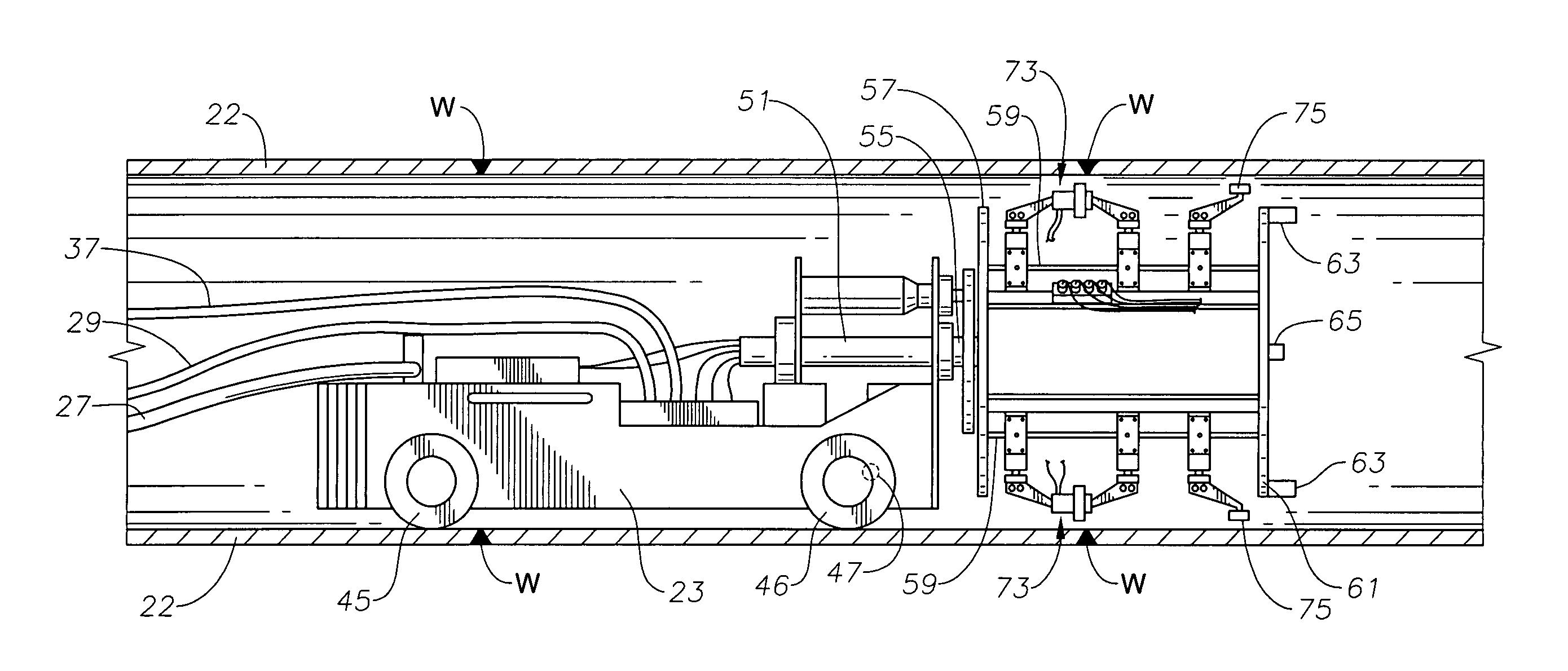
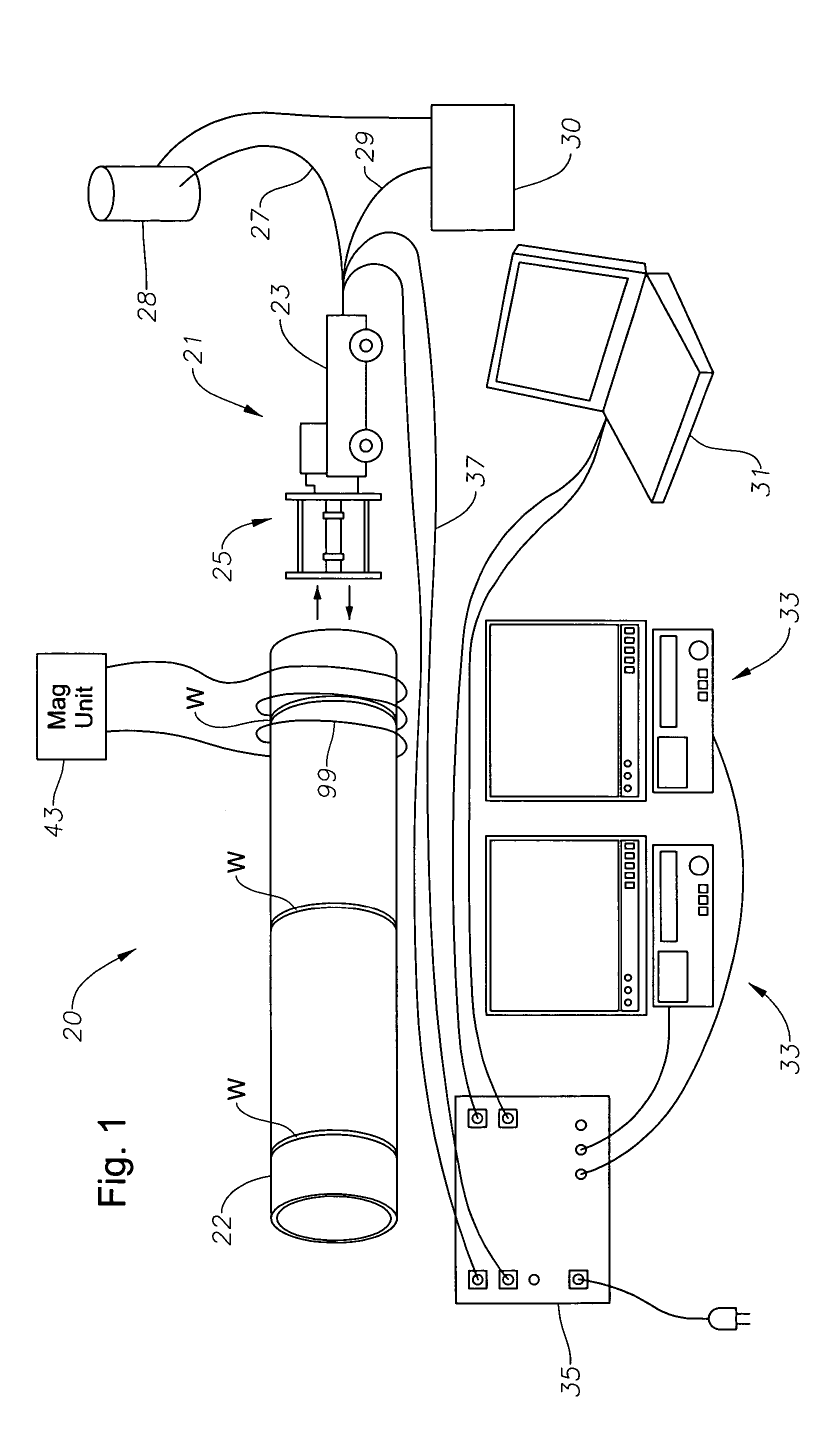
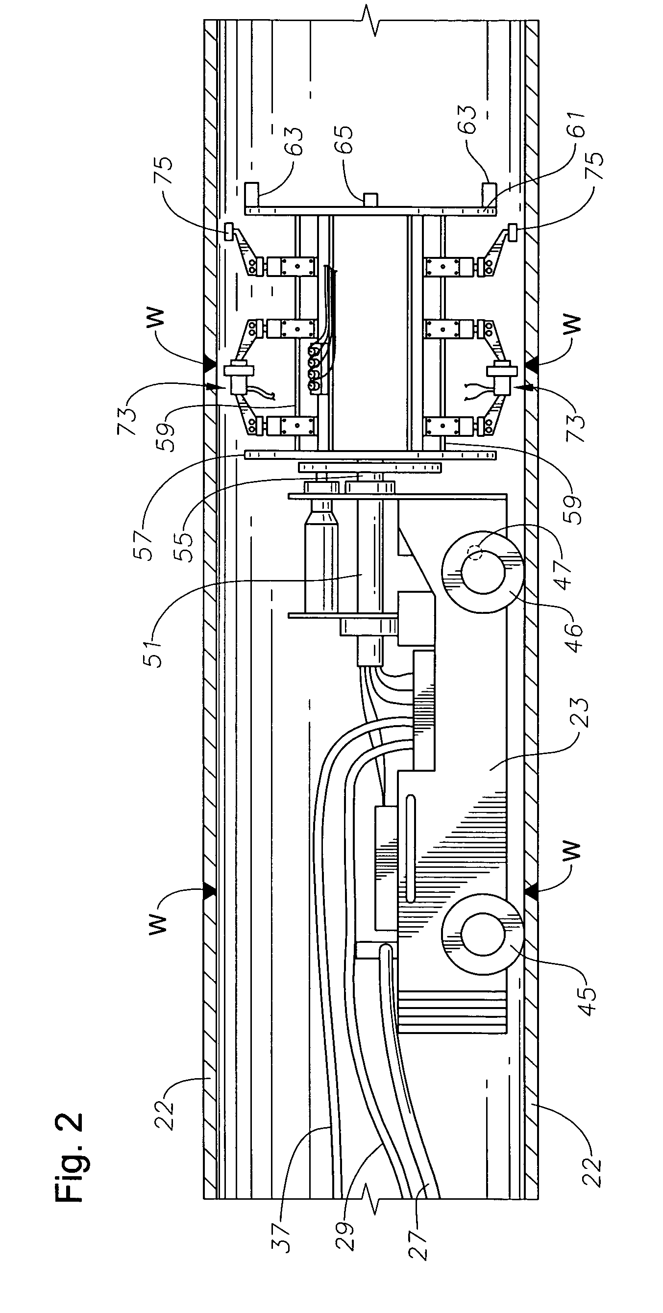
[0036]As illustrated in FIGS. 1–13, embodiments of the present invention advantageously provide a system, apparatus, and methods for inspecting a riser pipe from within the riser pipe through use of magnetic particle imaging “MPI.” For example, as perhaps best illustrated in FIG. 1, system 20 includes a self-propelled MPI scanning apparatus 21 having a drive unit 23 with a long...


PUM


Abstract

A system for inspecting a pipe weld from within a pipe through use of magnetic particle imaging “MPI” includes an apparatus having a head unit that carries a wire wheel brush for cleaning an inspection area along an inner diameter of a pipe weld, and an MPI medium dispenser for spraying an MPI medium upon the inspection area, both controlled by an operator. The head unit also includes a video inspection device controlled by the operator and used for viewing at least portions of the inspection area after being sprayed with the MPI medium and when under the influence of a magnetic field to determine if the weld has any defects. The head unit is connected to a drive unit. The drive unit includes a frame having a longitudinal axis and mounted on a set of drive wheels, and a set of support wheels spaced axially from the drive wheels. A linear drive motor mounted to the frame and coupled to the drive wheels moves the head unit linearly along an interior of the pipe between weld inspection areas to allow the operator to locate and inspect the welds from within the pipe.

Description

RELATED APPLICATIONS[0001]This application is a continuation-in-part of application Ser. No. 10 / 351,569 filed Jan. 24, 2003 now U.S. Pat. No. 6,904,818, which claims priority from the provisional application Ser. No. 60 / 370,444 filed Apr. 5, 2002 titled “Internal Riser Inspection Device.”BACKGROUND OF THE INVENTION[0002]1. Field of the Invention[0003]The invention relates in general to non-destructive testing of pipe, and in particular, to a test unit that is conveyed internally through pipe for magnetically inspecting the pipe for cracks or stresses and methods for inspecting associated therewith.[0004]2. Description of the Related Art[0005]Non-destructive testing of pipe has been done for many years utilizing magnetic particles, ultrasonic transducers, eddy current measurements, x-ray and other techniques. Operators using magnetic particle inspection techniques, typically with aid of an imaging device, can determine the existence of cracks or stresses and metal structures such as ...

Claims


Application Information

Patent Timeline
IPC IPC(8): G01N27/72G01R33/12E21BE21B47/00G01B17/02G01FG01M99/00G01N21/88G01N27/84G01N29/00G01N29/04G01N29/07G01N29/22G01N29/24G01N29/265
CPCG01B17/02G01N27/84G01N29/069G01N29/07G01N29/265G01N29/225G01N2291/2675G01N2291/02854G01N2291/105G01N2291/2636
Inventor HARTHORN, LARRY K.DIOQUINO, PEDRO A.
Owner HYDRIL USA DISTRIBUTION LLC
Why Eureka
Try Eureka