Engine control system

a control system and engine technology, applied in the direction of electrical control, process and machine control, instruments, etc., can solve the problems of unavoidable response lags and delays, large volume mentioned above, and large response lags, so as to improve estimation accuracy

Active Publication Date: 2006-09-19
NISSAN MOTOR CO LTD
View PDF17 Cites 52 Cited by
  • Summary
  • Abstract
  • Description
  • Claims
  • Application Information

AI Technical Summary

Benefits of technology

[0010]The prevent invention takes the above mentioned problems into consideration. One objective of the present invention is to provide a novel engine control system that can noticeably improve the estimation accuracy of the fresh intake air quantity and the intake air quantity that flows into the combustion chamber.

Problems solved by technology

It has been discovered that there are, however, unavoidable response lags and delays between the detected fresh intake air quantity values outputted by an airflow meter and the fresh intake air quantity that actually flows into the combustion chamber originating from the volume in the air intake passage from the airflow meter up to the combustion chamber.
Thus, the volume mentioned above tends to be large and response lag is also large.
Originating from this type of response lag is the danger that the control accuracy of settings such as fuel injection quantity that utilize the detected fresh intake air quantity value.
In particular, reductions in exhaust performance and power performance during transition periods such as acceleration and deceleration.
However, it was very difficult to estimate the fresh intake air quantity and the total intake air quantity that flow into the combustion chamber with good accuracy.

Method used


Image

  • Engine control system
  • Engine control system
  • Engine control system

Examples


Embodiment Construction

[0021]Selected embodiments of the present invention will now be explained with reference to the drawings. It will be apparent to those skilled in the art from this disclosure that the following descriptions of the embodiments of the present invention are provided for illustration only and not for the purpose of limiting the invention as defined by the appended claims and their equivalents.

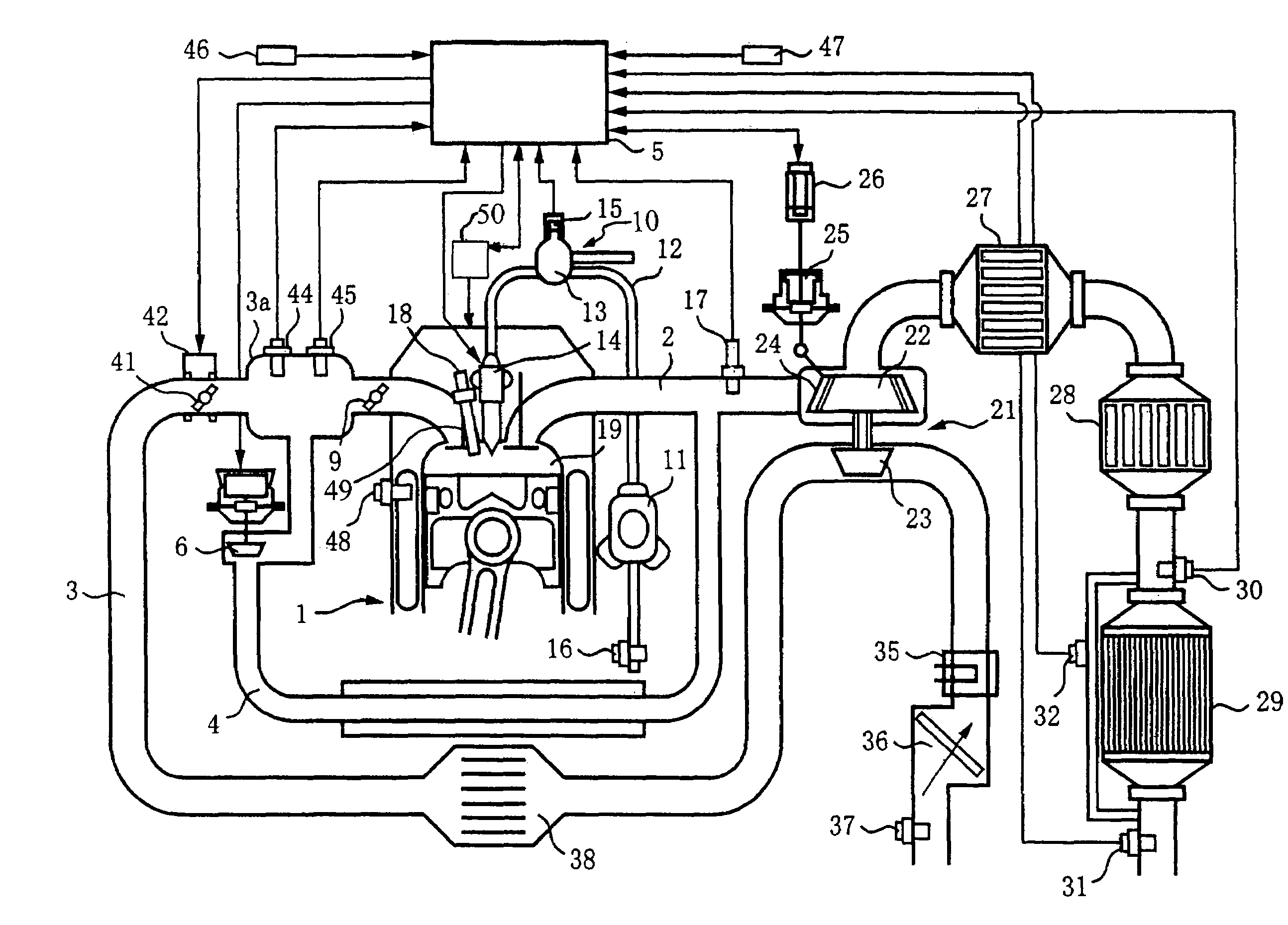
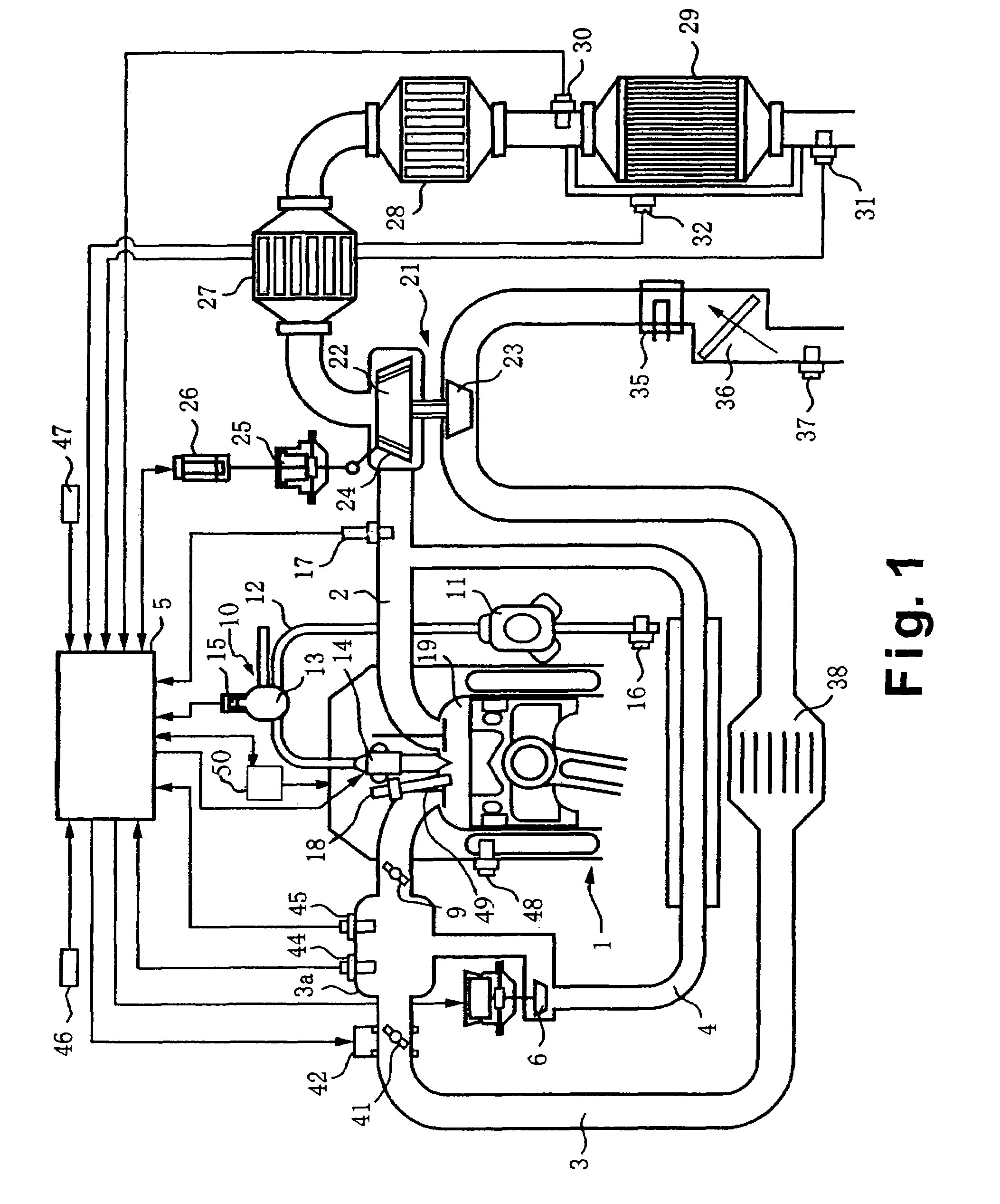
[0022]Referring initially to FIG. 1, an engine control system is illustrated for an internal combustion engine such as a supercharged diesel engine 1 in accordance with a first embodiment of the present invention. The engine control system in accordance with the present invention can be applied to other internal combustion engines used in automobiles and the like. The engine 1 preferably performs a comparatively large quantity of exhaust gas recirculation (EGR). In using the engine control system of the present invention, it is possible to noticeably improve the estimation accuracy of the estimated...


PUM


Abstract

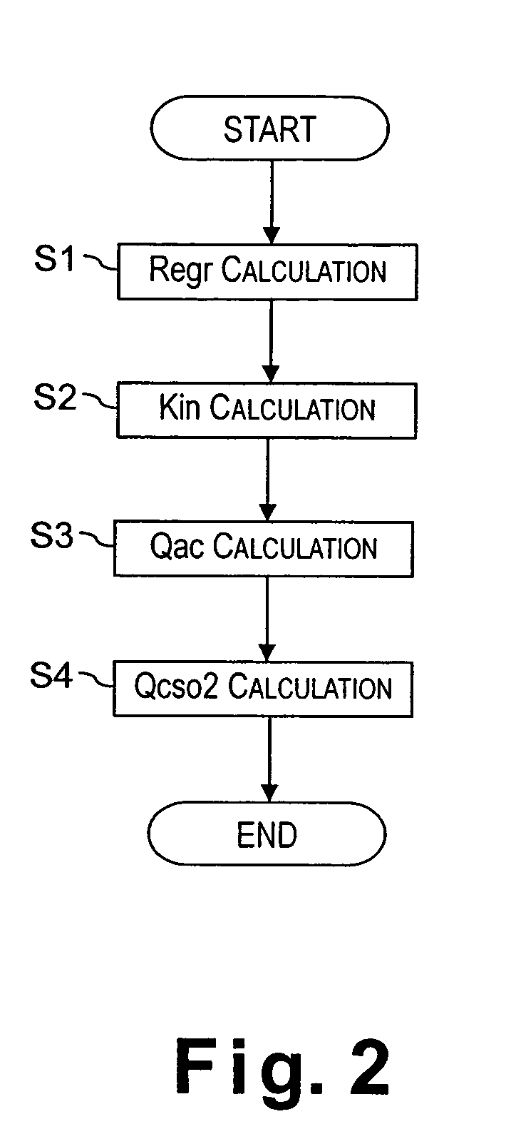
An engine control system is configured to improve the estimation accuracy of a fresh intake air quantity and a total intake air quantity that flows into the combustion chambers. The engine control system is configured to estimate an estimated EGR rate value Regr using a primary lag process for a target EGR rate, calculate a volumetric efficiency equivalency value based on the estimated EGR rate value Regr, estimate an estimated fresh intake air value Qac that flows into the combustion chamber based on a rate of change in a volumetric efficiency equivalency value Kin / Kinn-1 of the estimated EGR rate value Regr and the volumetric efficiency equivalency value Kin, and estimate an estimated total intake air quantity value Qsco2 that includes the EGR gas based on the estimated fresh intake air value Qac and the estimated EGR rate value Regr.

Description

BACKGROUND OF THE INVENTION[0001]1. Field of the Invention[0002]The present invention generally relates to an engine control system. In particular, present invention generally relates to a technology that aims to improve the estimation accuracy of fresh intake air quantity and total intake air quantity that flows into the combustion chamber.[0003]2. Background Information[0004]In internal combustion engines such as diesel engines, an exhaust gas recirculating system (EGR system) is widely used wherein a part of the exhaust gas is recirculated to lower the combustion temperature in order to reduce discharge of nitrogen oxide (NOx). In some conventional engine control system, an airflow meter is used in some diesel engines to detect fresh intake air quantity values and output the detected fresh intake air quantity values to an engine control system for maximum smoke limit control and EGR control.[0005]One example of such an engine control system is disclosed Japanese Laid-Open Patent ...

Claims


Application Information

Patent Timeline
Patent Type & Authority Patents(United States)
IPC IPC(8): F02D41/18F02M25/07F02B3/06F02B29/04F02D13/02F02D21/08F02D23/00F02D23/02F02D41/00F02D41/04F02D45/00
CPCF02D23/02F02M25/0754F02M25/0755F02B3/06F02B29/0406F02B2275/14F02D41/0072F02D41/187Y02T10/144F02D2041/1432F02D2200/0402F02D2200/0411F02M25/0707F02D2041/0017F02D41/0007F02D41/005F02D41/107F02D41/18F02D2041/001F02D2041/1431F02M26/05F02M26/46F02M26/47Y02T10/12Y02T10/40
Inventor ITOYAMA, HIROYUKI
Owner NISSAN MOTOR CO LTD
Why Eureka
Try Eureka