
Flat battery and production method therefor

a production method and battery technology, applied in the field of flat batteries, can solve the problems of insufficient battery capacity swelling of the outer case, etc., and achieve the effect of preventing inter-layer short-circuiting, preventing ions in low-pressure portions, and building up ions

Inactive Publication Date: 2006-09-19
PANASONIC CORP
View PDF9 Cites 23 Cited by
  • Summary
  • Abstract
  • Description
  • Claims
  • Application Information

AI Technical Summary

Benefits of technology

[0012]According to the construction of the first aspect of the invention, the positive electrode lead and negative electrode lead are located at different positions of the finished electrode plate group, so that there are no large variations in the distribution of a retaining force applied to the electrode plate group when it is accommodated inside the battery for keeping it in shape, and the positive and negative electrode plates remain in uniform facing state with each other. Also, because the positive and negative electrode leads are welded to the case through the space formed on both sides of the electrode plate group, the length of the leads are made shorter.
[0014]According to the method of manufacturing a flat battery of the second aspect of the invention, the electrode plate group of the coiled structure is formed in a flat shape having a rectangular plan by coiling around the positive and negative electrode plates with the separator therebetween, and the four corners thereof are cut off so that it is approximately octagonal. The electrode plate group is therefore accommodated inside the space having a circular plan made by the positive and negative electrode cases with less unoccupied space. This feature, coupled with the coiled structure, increases the facing area between the positive and negative electrode plates. Flat batteries having high load current characteristics are thus obtained.
[0016]According to the method of manufacturing a flat battery of the third aspect of the invention, the layer faces of the positive and negative electrode plates, which are coiled around into the electrode plate group of flat form with the separator therebetween, are formed in the shape corresponding to that of the accommodating space made by the positive and negative electrode cases. Thus, the electrode plate group is accommodated in the space with less unoccupied space. This feature, coupled with the coiled structure, increases the facing area between the positive and negative electrode plates. Flat batteries having high load current characteristics are thus obtained.
[0020]According to the method of manufacturing a flat battery of the fifth aspect of the invention, because the lead is welded to the case by series welding using a pair of welding electrodes abutted on the outer face of the case, sparks and dust generated during the welding do not scatter inside the case. Buildup of ions and internal short-circuiting resulting from sparks and dust scattered onto the electrode plate group or inside the case are thereby prevented. The reliability of flat batteries is thus improved by the welding method which is effective in increasing discharge characteristics of batteries.
[0024]According to the method of manufacturing a flat battery of the seventh aspect of the invention, by application of heat and pressure, the coiled intermediate product of the electrode plate group is formed into desired shape and dimensions corresponding to the accommodating space of electrode plate group. The pressure also causes the layering pressure of electrode plates uniform, whereby buildup of ions in low-pressure portions because of uneven pressure distribution is prevented, and also, when cutting the four corners of the intermediate product, inter-layer short-circuiting is prevented.

Problems solved by technology

This electrode plate group of coiled or layered structure can not be adopted to coin type batteries that have a circular plan, because accommodating rectangular electrode plate group in a circular positive electrode case results in insufficient battery capacity because of the low volume efficiency of the battery.
Another problem in constructing a battery using non-aqueous electrolyte such as a lithium ion rechargeable battery in a flat shape is that, if the electrode plate group of the coiled structure contains water, it generates hydrogen gas during the initial charge and discharge.
Water may also cause swelling of the electrode plates, which will lead to swelling of the outer case.
This may lead to buildup of ions in low-pressure portions or cause swelling of the outer case.
However, sparks thrown and dust scattered during the welding may cause internal short-circuiting or buildup of ions.

Method used


Image

  • Flat battery and production method therefor
  • Flat battery and production method therefor
  • Flat battery and production method therefor

Examples


Embodiment Construction

[0042]Preferred embodiments of the present invention will be described with reference to the accompanying drawings for a better understanding of the present invention. It should be noted that the embodiments described below are merely examples of carrying out the invention and should not pose any limitation on the technical scope of the invention.

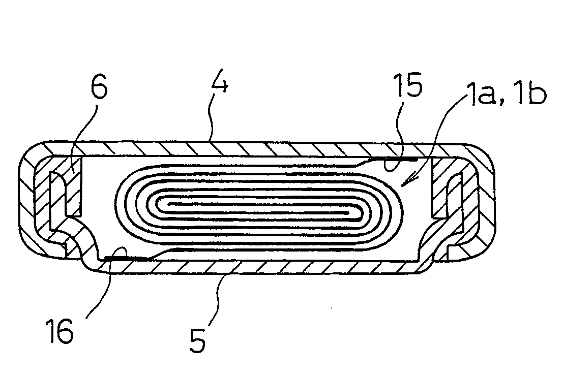
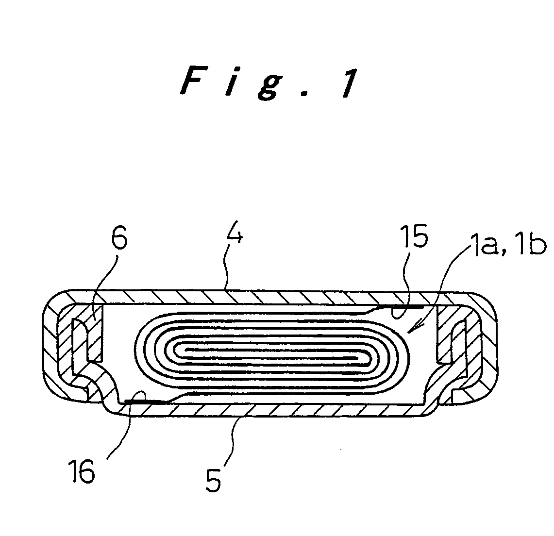
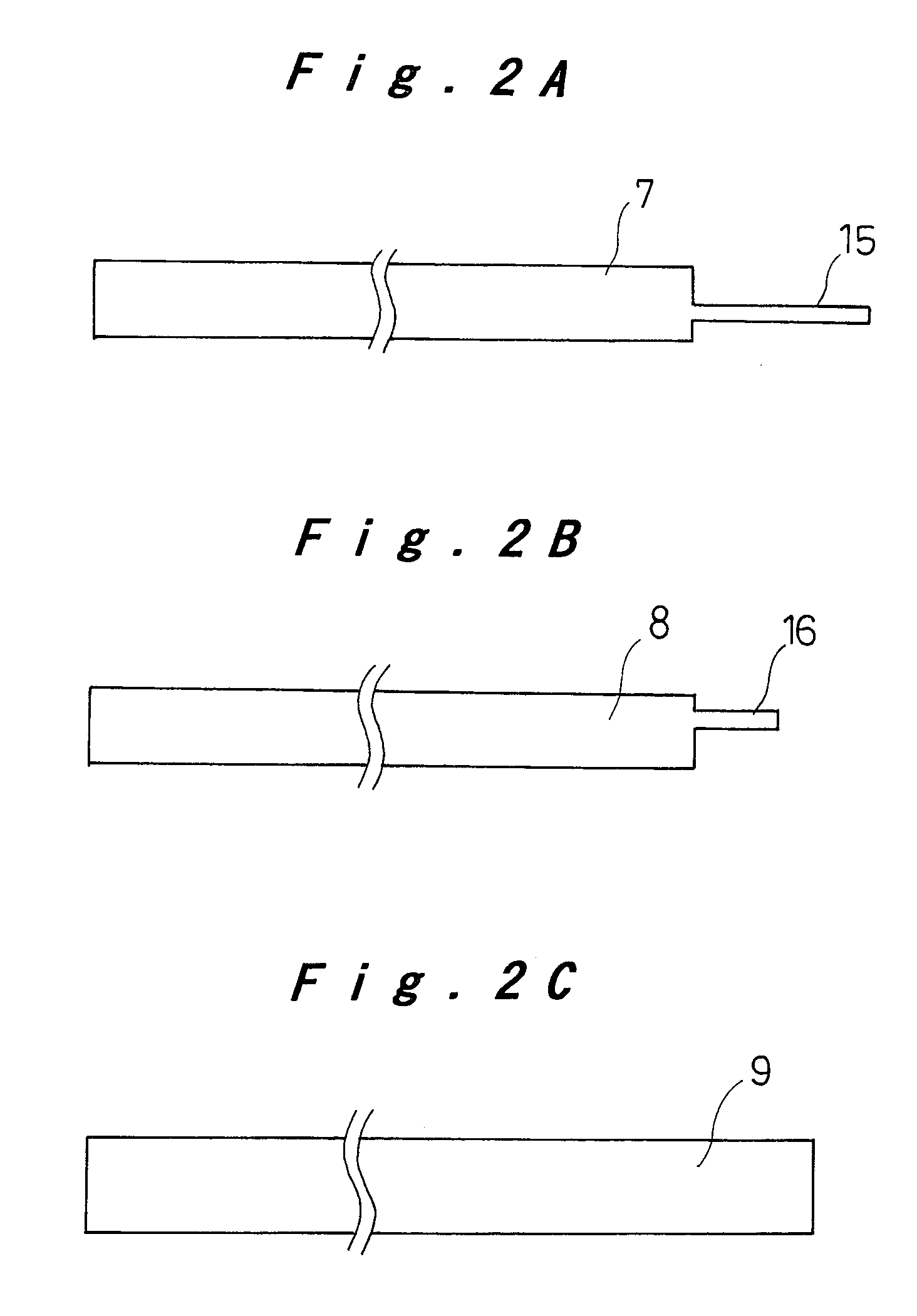
[0043]Flat batteries according to the embodiments described below are constructed, as one example, as lithium ion coin type rechargeable batteries. As shown in the cross section of FIG. 1, an electrode plate group 1a, 1b of a coiled structure, in which a positive electrode plate and a negative electrode plate are coiled around with a separator interposed therebetween, is accommodated in an inner space formed by coupling and sealing a positive electrode case 4 and a negative electrode case 5 of circular half shell form. The flat battery is thus formed in a coin shape to have high load current characteristics.

[0044]The electrode plate group 1...


PUM

PropertyMeasurementUnit
temperatureaaaaaaaaaa

Abstract

A positive electrode plate (7) and a negative electrode plate (8) are coiled around with a separator (9) interposed therebetween into a flat shape having a rectangular plan to obtain an intermediate product (17) of an electrode plate group, whose corners are then cut off along straight or curved lines to obtain a substantially octagonal electrode plate group (1a, 1b), so that it is accommodated in a negative electrode case (5) having a circular plan with good space efficiency. The problem of residual water in the coiled electrode plate group (1a, 1b, 1c) of a coin type battery having high load current characteristics is resolved by a vacuum dry treatment, and the problem of dust generated during the welding of leads is resolved by a method whereby dust is not scattered inside the case. Flat batteries with higher reliability are thus obtained.

Description

TECHNICAL FIELD[0001]The present invention relates to a flat battery having an electrode plate group of a coiled structure accommodated in a flat battery case made by coupling oppositely arranged open ends of a positive electrode case and a negative electrode case of half shell form, and a manufacturing method of this battery.BACKGROUND ART[0002]Flat batteries such as button type batteries and coin type batteries have widely been used as power sources for small or thin devices such as wrist watches and hearing aids or IC cards.[0003]FIG. 16 illustrates a conventional coin type battery, which is a typical flat battery. A positive electrode pellet 32 and a negative electrode pellet 33 of disk-like form are placed opposite each other with a separator 34 interposed between them inside a negative electrode case 35 of circular half shell form having a stepped lateral wall. Liquid electrolyte is injected into this case, a positive electrode case 31 is coupled to the open end of the negativ...

Claims


Application Information

Patent Timeline
Patent Type & Authority Patents(United States)
IPC IPC(8): H01M6/46H01M6/12H01M4/02H01M10/04H01M10/052H01M50/536H01M50/538
CPCH01M2/263H01M6/12H01M10/0431H01M2/0222H01M10/04Y10T29/49114H01M10/052H01M2004/025Y10T29/49108Y02E60/10H01M50/109H01M50/538Y02P70/50H01M50/536H01M10/0587H01M10/058
Inventor HAYASHI, TETSUYANAKANISHI, MAKOTO
Owner PANASONIC CORP
Learn More