Fluorometer with low heat-generating light source

a fluorometer and light source technology, applied in the field of instruments, can solve the problems of large amount of heat generated by instruments, many stand-alone fluorometers and those combined with other instruments, and difficulty in obtaining very high intensity light in the proper wavelength from instruments,

Inactive Publication Date: 2006-09-19
QUALICON DIAGNOSTICS LLC
View PDF30 Cites 26 Cited by
  • Summary
  • Abstract
  • Description
  • Claims
  • Application Information

AI Technical Summary

Problems solved by technology

Several difficulties exist with many stand-alone fluorometers and those combined with other instrumentation.
First, it is difficult to obtain very high intensity light in the proper wavelength from instruments which utilize a halogen or laser unitary light source without generating a large amount of heat.
Similarly, since tungsten lights and the like must be on continuously to reach and operate under stable conditions, they also generate a large amount of heat.
This large amount of heat can shorten the life of the lamp and should be dissipated because it may heat up the sample, thereby changing its fluorescent light emitting characteristics.
Thus, these types of instruments require extensive cooling for the light source, and such light sources require frequent replacement.
In addition, for those instruments in which a group of samples may be tested simultaneously, a great deal of excitation light energy can be lost through diversion between the samples.
This translates into a lower excitation efficiency.
Other fluorometers either lack sufficient sensitivity or are so expensive in construction as to be impractical for many purposes.
For example, many fluorometers with a halogen light source do not have adequate sensitivity.
This type of fluorometer has a limited dynamic range since all samples are illuminated and imaged at the same time if a typical charge coupled device (CCD) type camera is used.
A laser light source type fluorometer can have better performance, but the laser light source is more expensive.
This system is not suited to a standard 8 by 12 tray and is expensive because it requires complex positioning mechanisms to present the tubes to the fluorometry system.

Method used


Image

  • Fluorometer with low heat-generating light source
  • Fluorometer with low heat-generating light source
  • Fluorometer with low heat-generating light source

Examples


Embodiment Construction

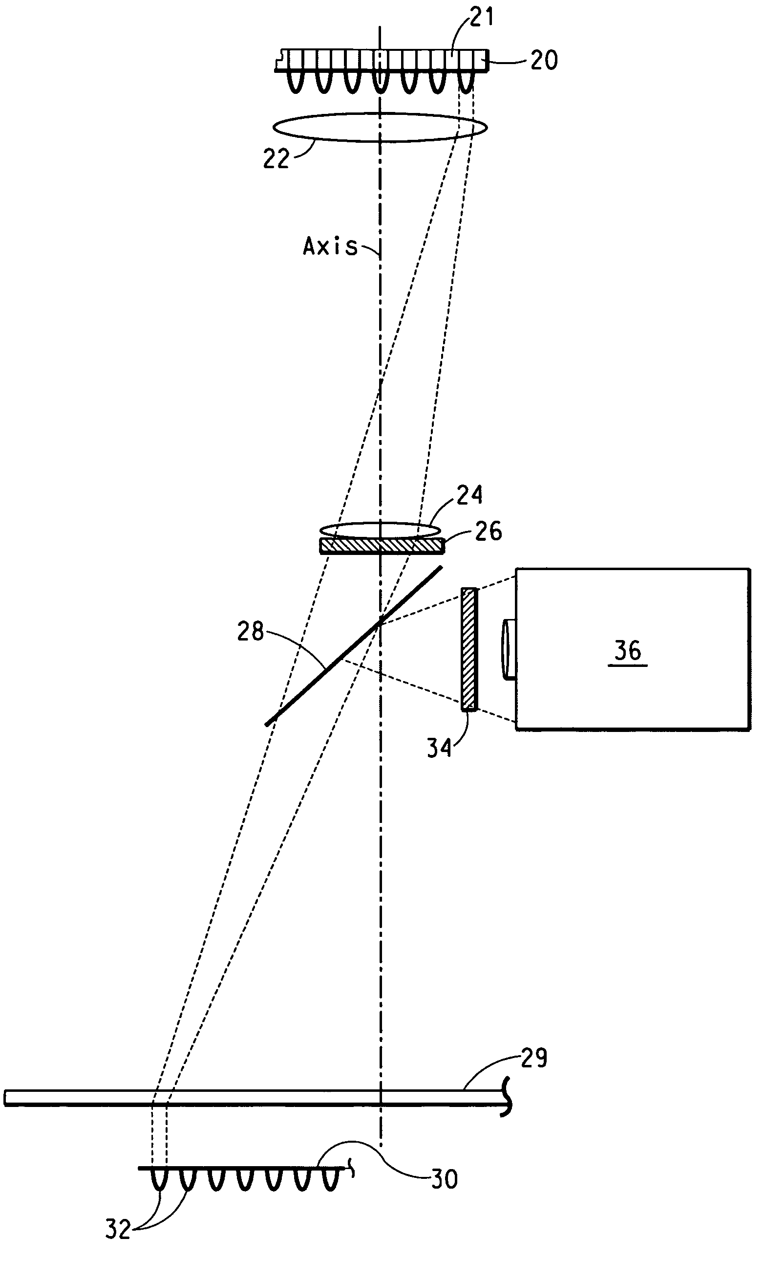
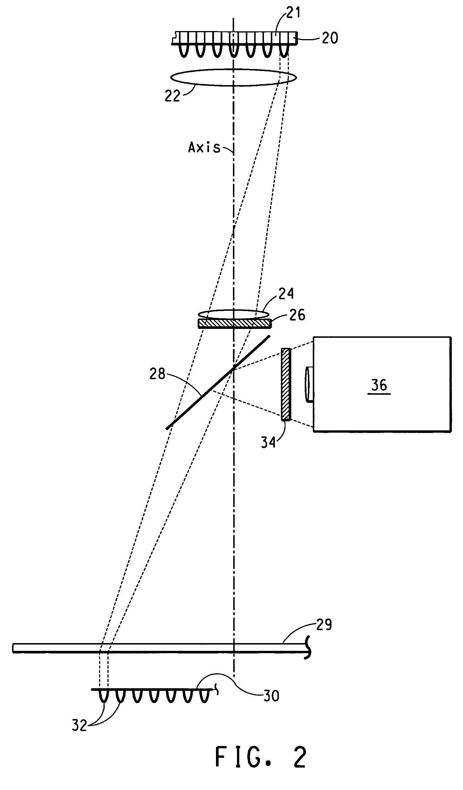
[0042]To circumvent the difficulties described above, the fluorometer of the present invention preferably uses a plurality of light emitting diodes (LEDs) as the light sources. By using LEDs, a large amount of heat is not generated, thereby minimizing sample heating, easing heat dissipation problems, and extending the life of the light source. In addition, by providing a one-to-one correspondence of light source to sample container with the directed light falling inside the container, waste of excitation energy is largely eliminated allowing for the use of a light source that uses minimal power.

[0043]In addition to the advantageous arrangement of components of the first and second optical paths means, the present invention also has the benefit that for the plurality of potentially fluorescing samples, there is an equal number of low heat-generating light sources, and the output of any one of the light sources is dedicated to a particular, correspondingly positioned container contain...


PUM

PropertyMeasurementUnit
temperaturesaaaaaaaaaa
thickaaaaaaaaaa
thickaaaaaaaaaa

Abstract

This invention concerns a fluorometer preferably combined with a thermal cycler useful in biochemical protocols such as polymerase chain reaction (PCR) and DNA melting curve analysis. The present fluorometer features a low heat-generating light source such as a light emitting diode (LED), having a one-to-one correspondence to each of a plurality of sample containers, such as capped PCR tubes in a standard titer tray. The fluorometer of the present invention further comprises an optical path between each LED and its correspondingly positioned container, and another optical path between each fluorescing sample within the positioned container and an optical signal sensing means. The instrument can be computer controlled.

Description

[0001]This application is a continuation of U.S. application Ser. No. 10 / 111,114, filed Apr. 19, 2002, which is a National Stage Application of PCT / US00 / 30771, filed Nov. 9, 2000, which claims the benefit of U.S. Provisional Application No. 60 / 165,267, filed Nov. 12, 1999.FIELD OF THE INVENTION[0002]This invention relates to instrumentation, particularly to instruments for detecting and measuring fluorescence, and more particularly to fluorescence measurements usable in conjunction with a variety of applications including use in assays based on polymerase chain reaction (PCR).BACKGROUND OF THE INVENTION[0003]Many reactions are characterized by the occurrence, or changes in level, of fluorescence when illuminated by a suitable excitation wavelength. In these types of reactions, a fluorescent sample absorbs light of a given wavelength and, in response thereto, emits light of a different wavelength.[0004]Fluorescence may be inherent in the involved reagents or it may be provided delibe...

Claims


Application Information

Patent Timeline
Patent Type & Authority Patents(United States)
IPC IPC(8): G21K5/00B01L7/00G01N21/25G01N21/64
CPCB01L7/52G01N21/6452G01N21/6456G01N21/6428B01L2300/0654B01L2300/1805Y10T436/143333G01N2201/062G01N21/64
Inventor LEE, JERALD D.DABELL, STANLEY D.
Owner QUALICON DIAGNOSTICS LLC
Why Eureka
Try Eureka