Damping for electromechanical actuators

a technology of electromechanical actuators and damping, applied in the direction of computer control, program control, instruments, etc., can solve the problems of reducing the life of system components, shimmy or oscillation of the nose wheel, damage to the system components, etc., and achieve the effect of substantially reducing the inertia of the electric motor

Inactive Publication Date: 2006-09-19
HR TEXTRON
View PDF31 Cites 32 Cited by
  • Summary
  • Abstract
  • Description
  • Claims
  • Application Information

AI Technical Summary

Benefits of technology

[0015]In accordance with a further aspect of the invention for the first and / or second embodiments, the inertia of the electric motor is substantially reduced in relation to typical motor inertia, by reducing the stator to rotor diameter ratio from a typical ratio of at or about 2:1 or less, to a substantially higher ratio than 2:1, e.g., from at or about 2.75:1, 3:1, 4:1, or 5:1 to as much as at or about 10:1, or more where possible. This low inertia motor is especially preferred for the current feedback version of the first embodiment of active damping, and also especially preferred for the second embodiment of passive damping.

Problems solved by technology

Nose wheels, like many other components, can be subject to shimmy or oscillation.
These oscillations, particularly when at or near the resonant frequency, can cause damage to system components, reduce their life, weaken control and hinder accuracy.
It has been found that such a high gear ratio causes the system to be generally unresponsive to damping.

Method used


Image

  • Damping for electromechanical actuators
  • Damping for electromechanical actuators
  • Damping for electromechanical actuators

Examples


Embodiment Construction

)

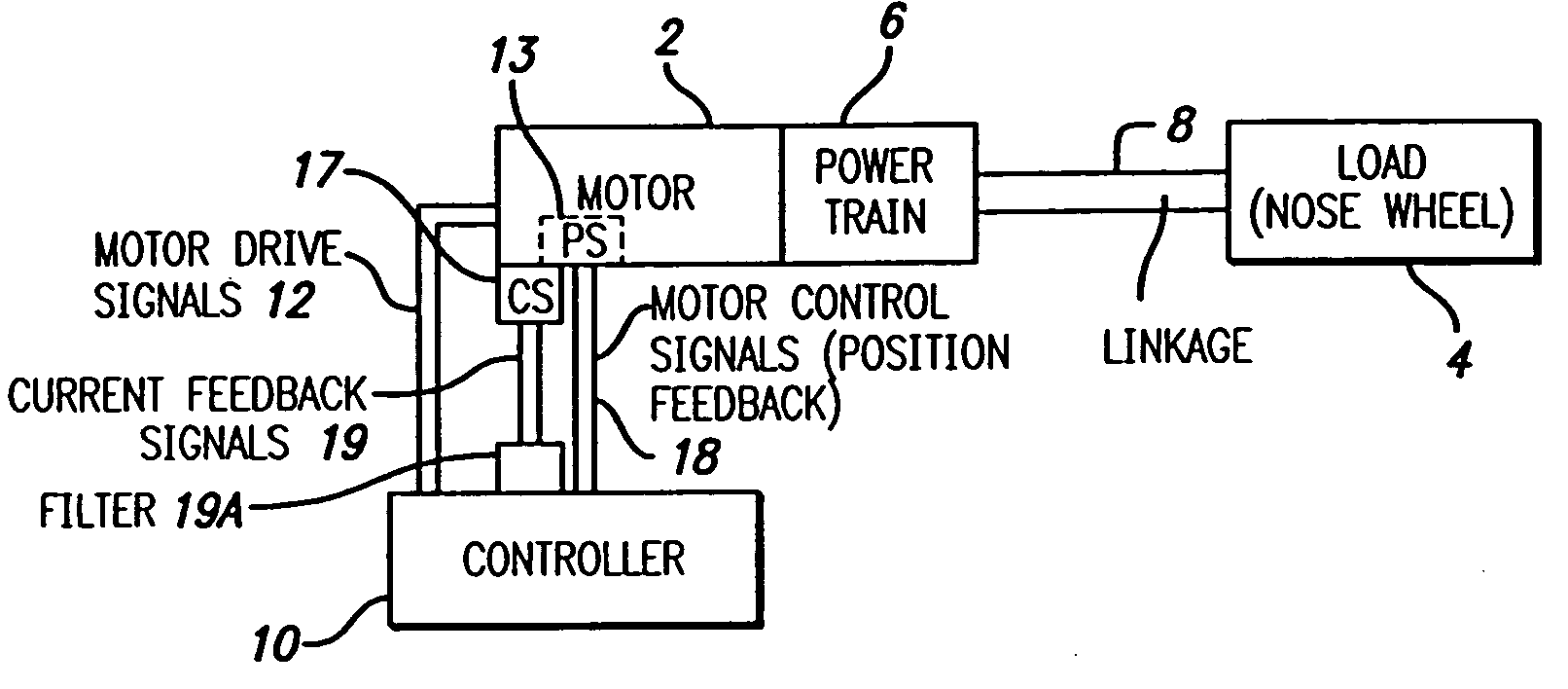
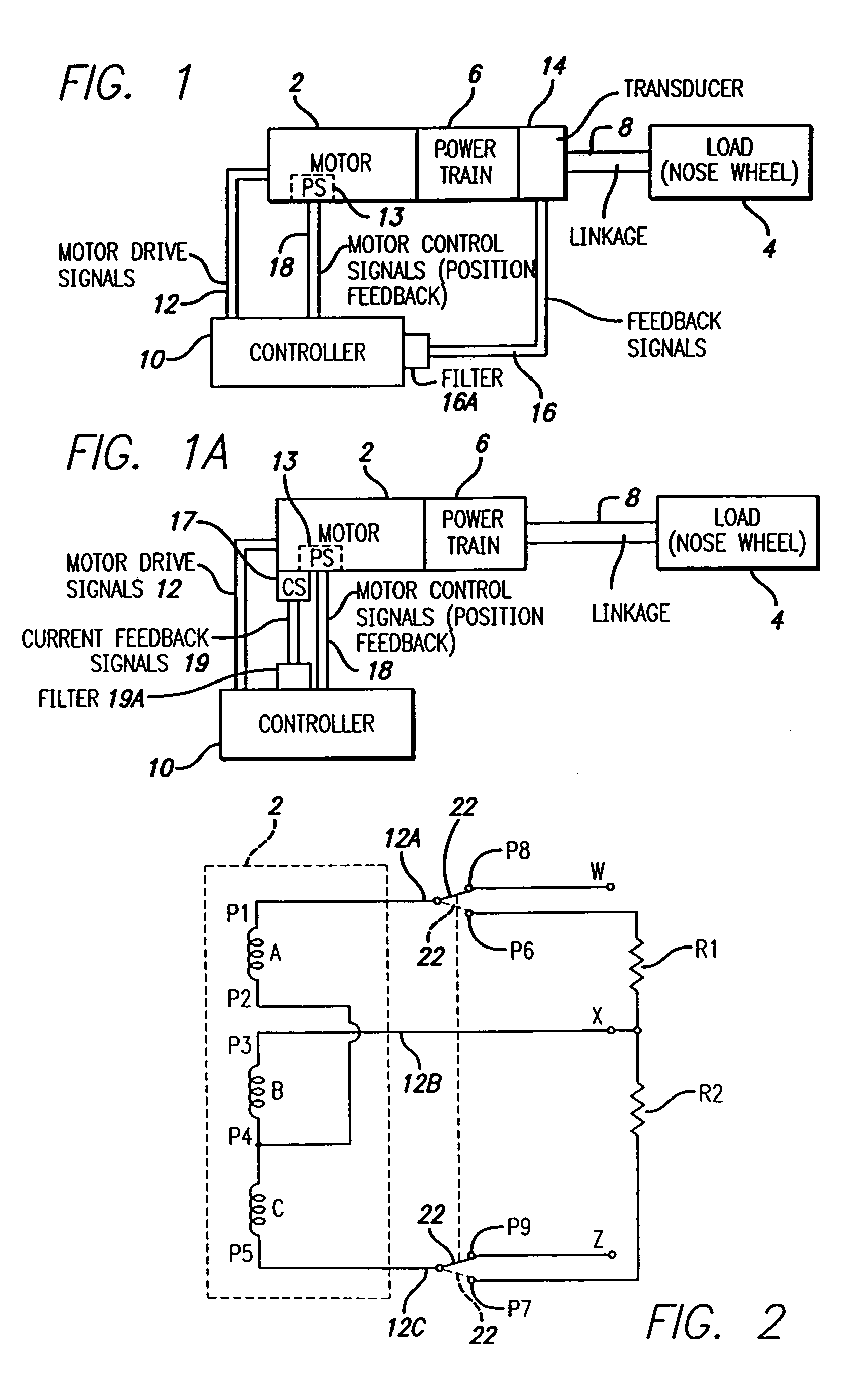
[0033]In a first embodiment of the invention, a steering control system for a load, e.g., an aircraft nose wheel uses an electric motor. Specifically, as shown in FIG. 1, a steering control system includes an electric motor 2 for moving a load 4 via a power train 6 and mechanical linkage 8. As is well known in the art, power train 6 typically ends in an output shaft (not shown) by which linkage 8 may connect to the power train 6.

[0034]A controller 10 sends motor drive signals 12 to motor 2 so that load 4 is driven to a desired position. A position sensor (PS) 13 senses position of load 4, e.g., by sensing the position of part of the motor or the motor output shaft as may be done in a typical servo motor. As is also typical, the position signals are used as motor control signals 18 which provide position feedback to a controller 10. If load 4 moves from the desired position, controller 10 is programmed to send motor drive signals 12 as necessary to move load 4 back to the desired po...


PUM


Abstract

Oscillation and other disturbance damping is provided for a system having a load driven by an electric motor, e.g., an electromagnetic actuator. Damping is achieved using feedback in an active mode, where power is supplied in a normal operation mode of the electromagnetic actuator. Feedback may be provided by measured force (or torque) transmitted between the actuator and load mass. A gear train or other mechanical advantage device may be connected between the electromagnetic actuator output and load, this combination forming an electromechanical actuator (EMA). Instead of force or torque, acceleration of the load may be used as a feedback signal. In one embodiment, active mode damping uses the motor's actual current as a feedback signal. In certain or all active damping versions of the invention, a high pass filter is preferably used to receive feedback signals and filter out low frequency feedback. Alternatively, damping is achieved in an inactive (passive) mode of motor operation, e.g., where the electric motor is not receiving power drive signals. The motor coils are shorted, e.g., using a switch. The induced motor currents act to inhibit load oscillations. Preferably, a resistance, e.g., a number of resistors, are in the short circuit to tailor the damping characteristics of the motor. In at least the active current feedback and passive modes of operation, inertia of the electric motor is substantially reduced in relation to typical motor inertia, by changing the stator to rotor diameter ratio from a typical ratio of at or about 2:1 or less, to a substantially higher ratio than 2:1.

Description

BACKGROUND OF THE INVENTION[0001]1. Field of the Invention[0002]The present invention relates to oscillation damping in systems having electric motors for moving and positioning a load, such as a nose wheel of an airborne vehicle.[0003]2. Description of the Related Art[0004]For a long time, hydraulic systems have been used to move and position various components of aircraft and other vehicles and devices. One application of hydraulics has been in aircraft nose wheel steering (moving the aircraft's front wheel to a desired angular position). Nose wheels, like many other components, can be subject to shimmy or oscillation. These oscillations, particularly when at or near the resonant frequency, can cause damage to system components, reduce their life, weaken control and hinder accuracy. Accordingly, it is desirable to dampen vibrations of the load. Damping is often achieved when hydraulic power is used by forcing hydraulic fluid through an orifice.[0005]It is desirable to use electric...

Claims


Application Information

Patent Timeline
Patent Type & Authority Patents(United States)
IPC IPC(8): G05B5/01G05B19/404H02P5/00
CPCG05B19/404G05B2219/49054
Inventor EDSON, RALPH D.MOCK, M. ROBERT
Owner HR TEXTRON
Why Eureka
Try Eureka