Generating different delay ratios for a strobe delay

Active Publication Date: 2006-09-19
ORACLE INT CORP
View PDF3 Cites 18 Cited by
  • Summary
  • Abstract
  • Description
  • Claims
  • Application Information

AI Technical Summary

Benefits of technology

[0007]A digital delay-locked loop has been discovered having a reduced area as compared to typical register-controlled delay-locked loops (RDLLs) used to control strobe delay lines that provide delay to strobe signals driving asynchronous FIFOs. This result is achieved by reducing ratio computation (i.e. gear logic) circuitry of the RDLL. A master delay line receives a control code to delay a reference clock by one clock period. A slave delay line receives the control code to delay a strobe signal by a predetermined fraction of the clock period. The master delay line may include individual sections responsive to the control code which effectively delay a signal by a portion of the clock period, the delay having a fixed relationship to a delay associated with individual sections of the slave delay line.
[0008]In some embodiments of the present invention, an integrated circuit includes a first delay circuit and a second delay circuit coupled to receive a control code. The control code configures the first delay circuit to delay a reference clock signal by one clock period. The control code configures a second delay circuit to delay a signal by a predetermined fraction of the clock period.
[0009]In some embodiments of the present invention, a method inc

Problems solved by technology

Due to the complexity of implementing mathematical operations, the g

Method used


Image

  • Generating different delay ratios for a strobe delay
  • Generating different delay ratios for a strobe delay
  • Generating different delay ratios for a strobe delay

Examples


Embodiment Construction

)

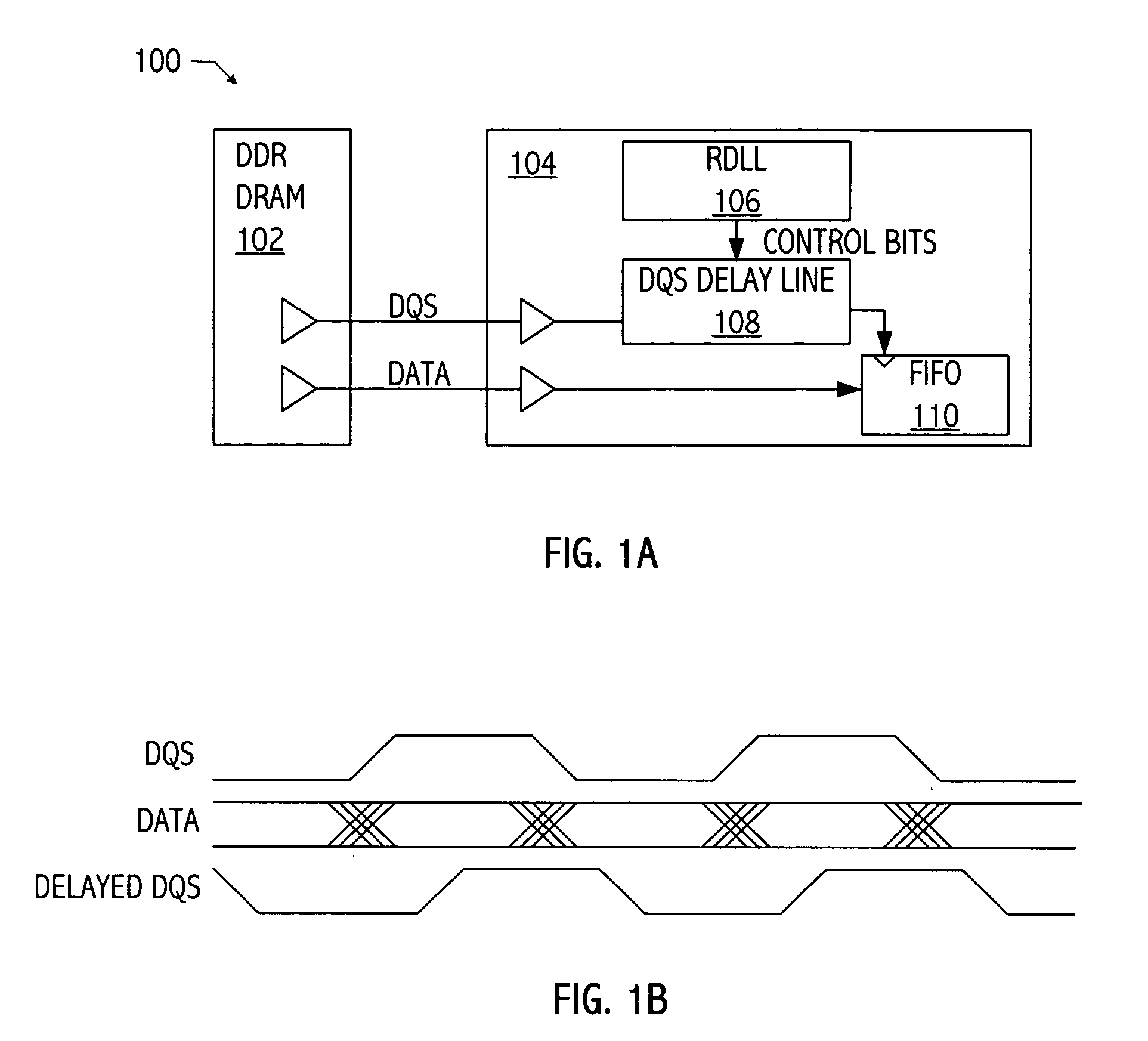
[0023]Referring to FIG. 1A, an exemplary memory system (i.e., memory system 100) includes a dual-data rate dynamic random access memory (i.e., DDR DRAM 102) coupled to a memory interface 104. Memory interface 104 includes a master register delay-locked loop (i.e., RDLL 106) coupled to a slave strobe delay line (i.e., DQS delay line 108). DQS delay line 108 delays a strobe signal (i.e., DQS) by an amount specified by control bits received from RDLL 106. As illustrated in FIG. 1B, the delayed strobe signal (i.e., delayed DQS) clocks data from DDR DRAM 102 into state elements included in FIFO 110, when the data has stabilized, according to the delayed DQS signal.

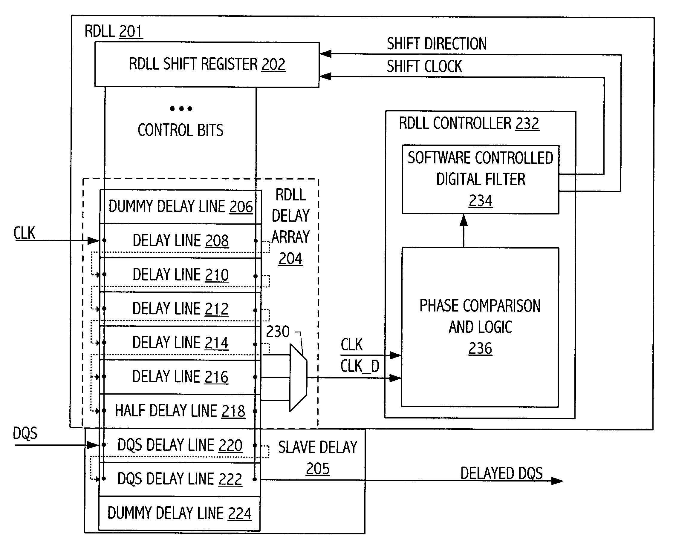
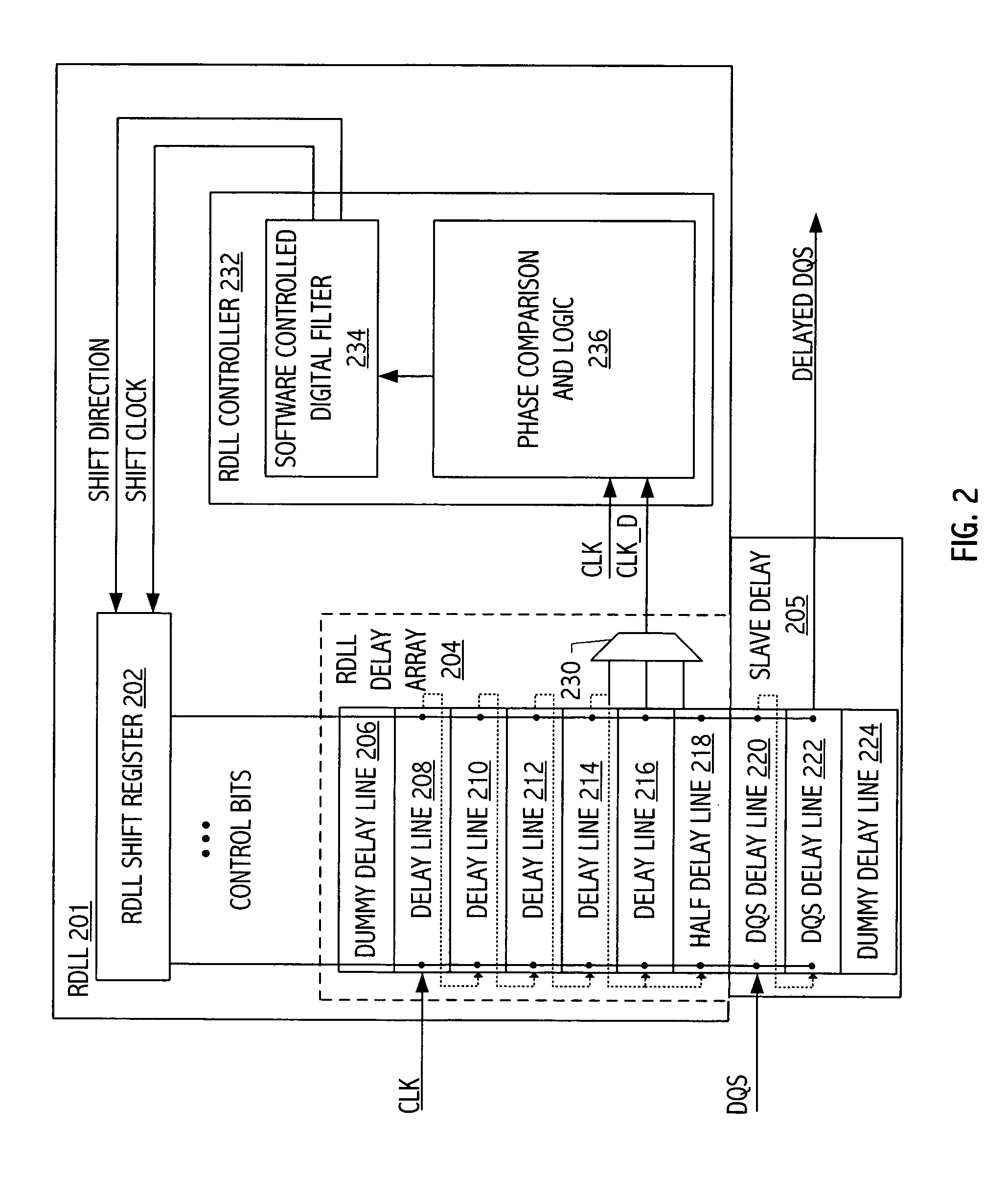
[0024]An exemplary RDLL, e.g., RDLL 201, coupled to a slave delay line, e.g., slave delay 205, is illustrated in FIG. 2. RDLL delay array 204 includes a plurality of delay lines, e.g., delay lines 206, 208, . . . , 218. Delay lines 208, 210, . . . , 218 are coupled in series, i.e., the output of delay line 208 is coupled to th...


PUM


Abstract

A digital delay-locked loop has been discovered having a reduced area as compared to typical register-controlled delay-locked loops (RDLLs) used to control strobe delay lines that provide delay to strobe signals driving asynchronous FIFOs. This result is achieved by reducing ratio computation (i.e. gear logic) circuitry of the RDLL. A master delay line receives a control code to delay a reference clock by one clock period. A slave delay line receives the control code to delay a strobe signal by a predetermined fraction of the clock period. The master delay line may include individual sections responsive to the control code which effectively delay a signal by a portion of the clock period, the delay having a fixed relationship to a delay associated with individual sections of the slave delay line.

Description

CROSS-REFERENCE TO RELATED APPLICATION(S)BACKGROUND[0001]1. Field of the Invention[0002]The present invention relates generally to techniques for delaying a signal, and more particularly, to digital delay-locked loops.[0003]2. Description of the Related Art[0004]Integrated circuit microprocessors typically interface to off-chip memory circuits (e.g., synchronous dynamic random-access memory, i.e., ‘SDRAM’) that transmit a strobe clock and data to the microprocessor. The strobe and data signals transmitted by the memory transition at the same time, i.e., the strobe and data are edge-aligned. Data may be transmitted on both rising and falling edges of the strobe or clock. In order to sample data in the middle of the data valid region, an on-chip memory interface typically delays the strobe. The strobe delay may be implemented in digital circuitry by a delay line controlled by a delay-locked loop (DLL), (e.g., a digital DLL).[0005]Digital DLLs typically include a digital delay line and...

Claims


Application Information

Patent Timeline
IPC IPC(8): H03L7/06
CPCH03L7/0805H03L7/085H03L7/0814
Inventor AMICK, BRIAN W.RAMACHANDRAN, APARNAYOON, DONG J.TRAN, TRI K.SINGH, GAJENDRA P.GAUTHIER, CLAUDE R.
Owner ORACLE INT CORP
Why Eureka
Try Eureka