System and method for a composite lens for a flow cytometer

a flow cytometer and composite lens technology, applied in the field of optical lens systems, can solve the problems of less image quality and not the same amount of image quality required previously, and achieve the effects of reducing the overall curvature value, and reducing the size of the lens

Active Publication Date: 2006-09-19
BECKMAN COULTER INC
View PDF40 Cites 45 Cited by
  • Summary
  • Abstract
  • Description
  • Claims
  • Application Information

AI Technical Summary

Benefits of technology

[0010]The above mentioned targets are realized with a lens system, disclosed herein, for collecting light from an object housed within a cuvette, wherein the cuvette wall thickness is minimized so that light collection can begin spatially closer to the object. The thin cuvette wall, from 0.75 to 1.50 mm thick, in this system allows for greater light collection while maintaining a small diameter for the ensuing optical elements. A positive plano-convex lens is cemented to the cuvette surface such that the planar surfaces are mated. This lens is approximately hemispherical with the radius of curvature of the lens being similar to its thickness. Following the plano-convex lens is a first group of lenses comprising a series of at least three meniscus lenses all with concave surfaces facing toward the object. The subsequent lenses have a radius of curvature that increases with distance from the object. A final group of lenses optically coupled to the last one of the series of meniscus lenses comprises an achromatic compound lens. In one embodiment, the achromatic compound lens may comprise either a pair of doublet lenses wherein the first doublet lens comprises a biconvex profile and a second doublet lens comprising a concavo-convex profile. In another embodiment, the achromatic compound lens may comprise a triplet lens consisting of a first biconvex lens; a second biconvex lens; and a biconcave lens coupled between the first and second biconvex lenses.

Problems solved by technology

However, flow cytometers are typically not vision systems and the same amount of image quality has not previously been required to achieve adequate results on a cytometer.
However, this is a lesser level of image quality than what is required when the sensing device is the human eye as is the case in many microscopes.

Method used


Image

  • System and method for a composite lens for a flow cytometer
  • System and method for a composite lens for a flow cytometer
  • System and method for a composite lens for a flow cytometer

Examples


embodiment no.1

Preferred Embodiment No. 1

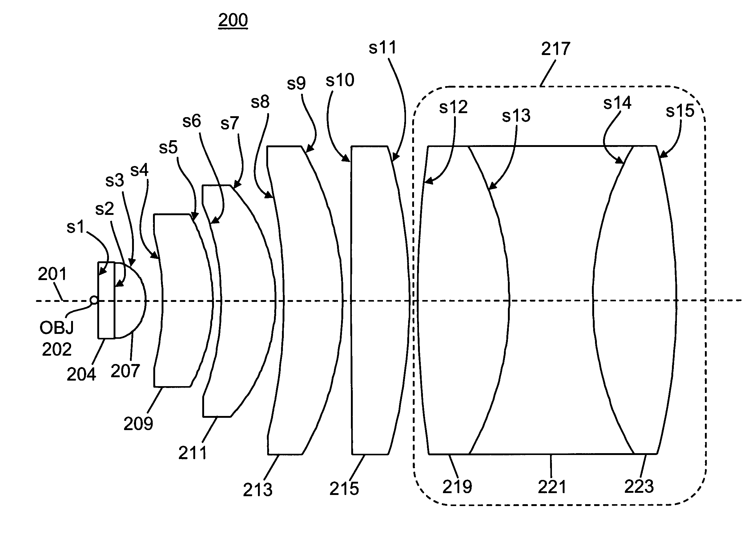
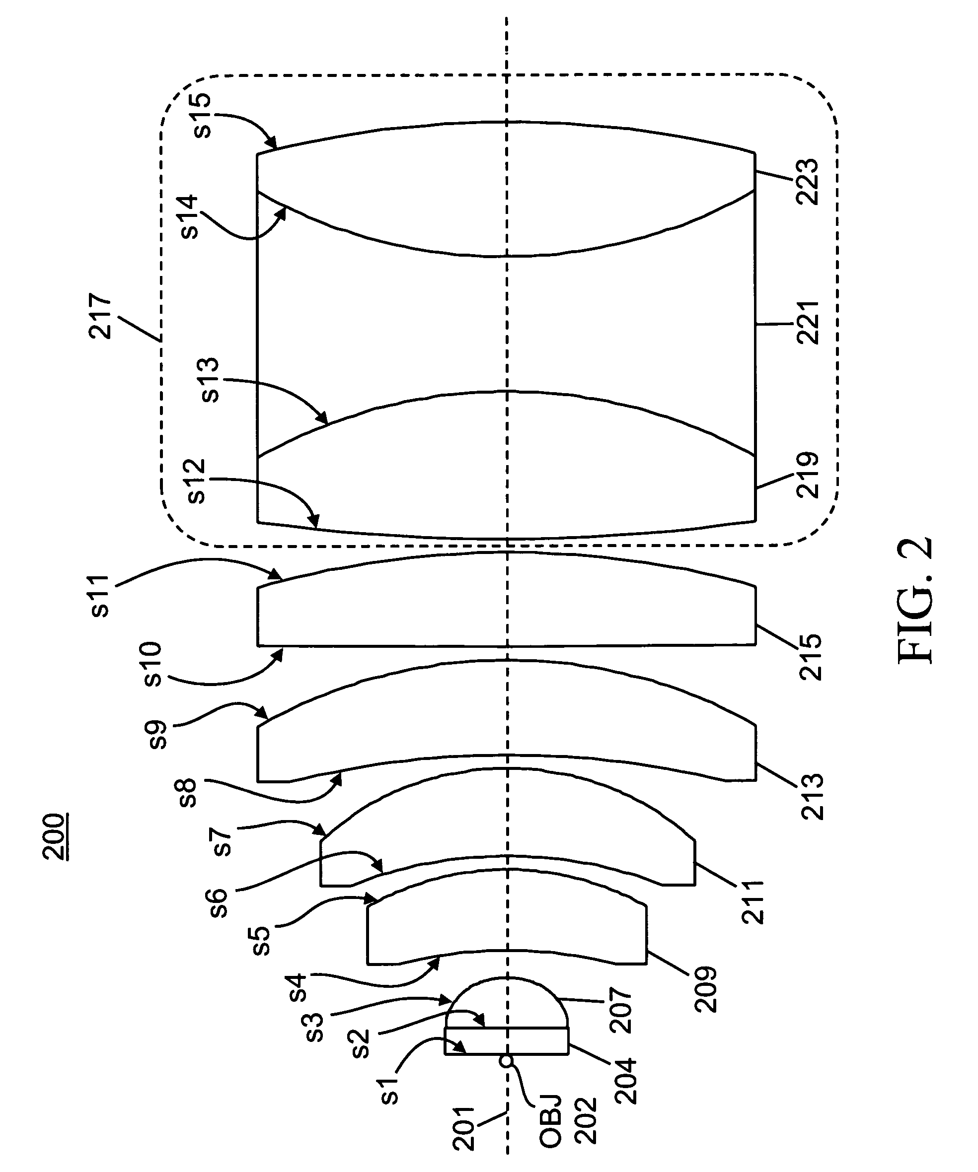
[0018]A first preferred embodiment of a cytometry lens system 200 in accordance with the present invention is shown in FIG. 2. The reference marks beginning with the letter “s” in FIG. 2 correspond to the surfaces defined in Table 1. Table 1 contains detailed lens data relating to the preferred embodiment 200. The values of radius of curvature, thickness and aperture provided in Table 1 are in units of millimeters. Entries in the column labeled “Thickness” refer to the distance measured from where the surface in question intersects the axial line 201 (FIG. 2) to where the subsequent surface listed in Table 1 (the surface to the right of the one in question in FIG. 2) intersects this same line. Thus, if the surface in question is on a left side of a lens element (according to the orientation shown in FIG. 2), then the “thickness” entry refers to the thickness of the lens element measured along the axial line 201. If the surface in question is on the right si...

embodiment no.2

Preferred Embodiment No. 2

[0027]A second preferred embodiment of a cytometry lens system 300 in accordance with the present invention is shown in FIG. 3. The reference marks beginning with the letter “s” in FIG. 3 correspond to the surfaces defined in Table 2. Other parameters listed in Table 2 are defined similarly to the respective parameters in Table 1, as already discussed above.

[0028]

TABLE 2Radius ofThick-Index ofAbbeSurfaceCurvaturenessApertureMaterialRefractionNumberOBJ—0.1250.141.33342.530s16—1.0002.00Crown1.45850.510Glasss17—1.9001.90Crown1.45850.510Glasss18−2.0001.0681.90Air1.000—s19−10.0003.0003.50Crown1.51647.830Glasss20−7.5000.5004.50Air1.000—s21−12.0003.5005.00Crown1.51647.830Glasss22−9.1100.5006.50Air1.000—s23−34.5004.0007.00Crown1.51647.830Glasss24−10.9000.5007.50Air1.000—s2523.0005.0008.00Crown1.51647.830Glasss26−23.0003.0008.00Flint1.68922.480Glasss27−26.4001.5007.50Air1.000—s28−14.3603.0008.00Flint1.68940.221Glasss2914.3605.5006.75Crown1.51922.480Glasss30−16.58483...


PUM


Abstract

A lens system for collecting and focusing light emanating from an object has a cuvette housing the object and having a wall of thickness not greater than 1.5 millimeters; a plano-convex lens having a planar surface affixed to the wall; a sequence of at least three meniscus lenses, each meniscus lens having a concave surface toward the object and a convex surface, each successive meniscus lens receiving the light from the immediately preceding meniscus lens and having radii of curvature of its concave and convex surfaces greater than corresponding radii of the preceding meniscus lens; and at least one compound lens that may be a doublet lens or a triplet lens, the compound lens receiving the light from a last meniscus lens, wherein an image of a geometrical point on the object has a root-mean square spot size equal to or less than 63 μm.

Description

FIELD OF THE INVENTION[0001]The present invention relates generally to optical lens systems that are used for studying the interaction of microscopic particles with electromagnetic radiation. More particularly, the present invention relates to an optical lens system for use in a flow cytometer, wherein the lens system captures and transmits scattered light, fluorescence or other electromagnetic radiation to one or more sensing devices.BACKGROUND OF THE INVENTION[0002]In a flow cytometer, particles of interest (i.e. cells, beads, or other microscopic objects) are transported in a carrier fluid though a cuvette or flow cell. As is well known in the art, some of these particles may be non-fluorescent whereas others may be marked with fluorescent labels that can be used to identify specific particle characteristics or may hold an inherent autofluorescence characteristic which, when excited, can cause emission of electromagnetic radiation (such as photon irradiation or emission).[0003]La...

Claims


Application Information

Patent Timeline
Patent Type & Authority Patents(United States)
IPC IPC(8): G02B9/00G02B9/62
CPCG02B21/02G01N2015/144
Inventor SAUTER, MEGAN LYNNESHARPE, JOHNATHAN CHARLESPIEPER, SEAN B.
Owner BECKMAN COULTER INC
Why Eureka
Try Eureka