Orthogonal chirp modulation in multipath environments

a multipath environment and orthogonal chirp technology, applied in the field of communication, can solve the problems of unfavorable wireless telephone system, inability to achieve the desired orthogonality, and inability to achieve the desired spatial diversity, etc., to achieve the desired orthogonality, reduce transmission errors, and mitigate bandwidth usage

Active Publication Date: 2006-09-19
TEXAS INSTR INC
View PDF22 Cites 14 Cited by
  • Summary
  • Abstract
  • Description
  • Claims
  • Application Information

AI Technical Summary

Benefits of technology

[0012]One aspect of the present invention provides systems and methods for implementing orthogonal chirp signals, such as for use in multipath environments. A chirp signal is generated for transmission, such that delayed versions of the chirp signal in a transmitted signal are substantially orthogonal to the chirp signal itself. To facilitate the desired orthogonality, the chirp signal has a chirp rate, which can be selected to reduce transmission errors and mitigate bandwidth usage. When the transmitted signal is received, which generally includes noise and delayed versions due to multipath interference, noise and the effects of the multipath environment can be easily removed to obtain the chirp signal.
[0013]Thus, another aspect of the present invention provides a communication system

Problems solved by technology

Regardless of the type of communications system being employed, noise, distortion and multipath interference are often introduced into data signals transmitted over an associated communications path, including both wired and wireless systems.
Multipath interference is the unwanted addition of one or more signals to a desired signal.
However, spatial diversity is not usually feasible for mobile station communication systems.
For example, a wireless telephone system would not work well if a user was required to set up multiple antennas spaced apart from each other.
However, these methods all have problems dealing with multipath interference.
Using QAM with DEF requires a formidable amount of hardware and generally does not work well in dense multipath envir

Method used


Image

  • Orthogonal chirp modulation in multipath environments
  • Orthogonal chirp modulation in multipath environments
  • Orthogonal chirp modulation in multipath environments

Examples


Embodiment Construction

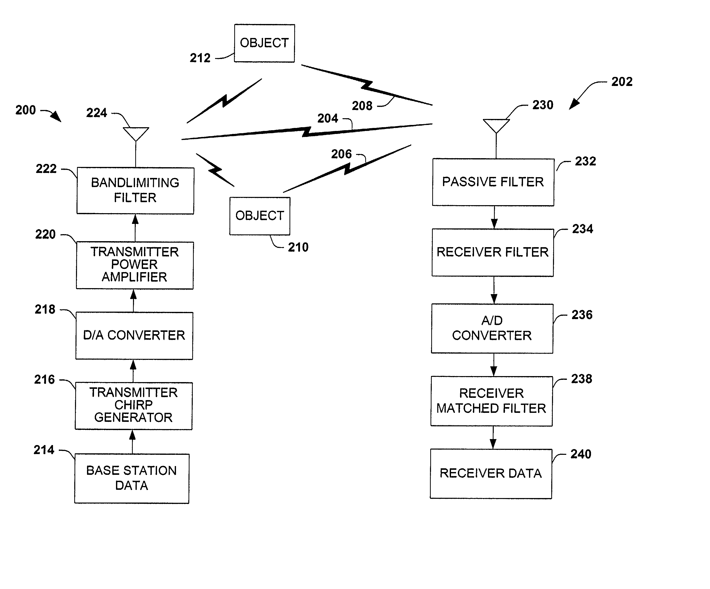
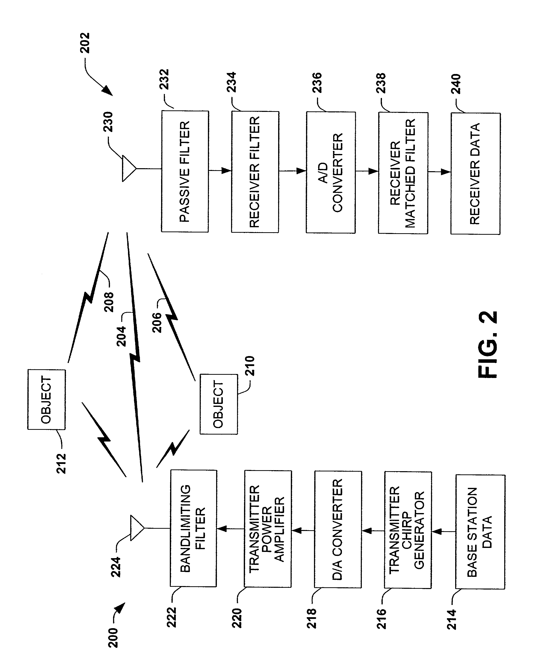
[0038]FIG. 2 illustrates an orthogonal chirp communication system according to one aspect of the invention. The communication system has a base station 200 and a receiving station 202. The base station 200 employs analog chirp signals to send data from the base station 200 to the receiving station 202. The base station 200 and receiving station 202 can simply be a transmitter and receiver, respectively. The analog chirp signals used are relatively narrowband, which means that the analog chirp signals vary in frequency by less than the carrier frequency. Some typical examples of narrowband frequencies are 1 MHz, 3 MHz, 6 MHz, 10 MHz and the like. However, other frequencies can be narrowband. Additionally, it is appreciated that analog chirp signals that are not narrowband can still be used according to aspects the present invention. The only upper limit on usable frequencies is due to atmospheric conditions causing atmospheric attenuation. For applications without atmospheric attenua...


PUM


Abstract

Methods and systems for communication systems are disclosed. Chirp signals generated according to a chirp rate and carrier frequency are used for communication. The chirp rate can be determined by solving integrals or by simulation of transmission parameters. A chirp signal is transmitted from a base station and delayed versions of the chirp signals are created. The delayed versions are generated by the chirp signal reflecting off of reflectors. A receiving station receives an incoming signal. The incoming signal includes the LOS signal plus delayed versions, noise and/or interference. Unwanted signals, either LOS or delayed versions, noise and/or interference are removed from the incoming signal to obtain the desired chirp signal. Using the chirp rate, the chirp signal is converted to a corresponding digital signal.

Description

TECHNICAL FIELD[0001]The present invention relates generally to communications and, more particularly, to systems and methods for orthogonal chirp modulation for communications in multipath environments.BACKGROUND OF THE INVENTION[0002]Various techniques have been developed to facilitate communication of data signals over an associated communications path. The particular communications protocol employed generally depends on the transmission medium, the available bandwidth resources, and other design considerations. Regardless of the type of communications system being employed, noise, distortion and multipath interference are often introduced into data signals transmitted over an associated communications path, including both wired and wireless systems.[0003]Multipath interference is the unwanted addition of one or more signals to a desired signal. Multipath signals are generated by reflectors such as buildings, cars, signs, etc., which the signal bounces off of generating a delayed...

Claims


Application Information

Patent Timeline
IPC IPC(8): H04B1/69
CPCH04B1/69H04B2001/6912
Inventor HOOTON, THOMAS R.
Owner TEXAS INSTR INC
Why Eureka
Try Eureka