
Apparatus for harming or killing fouling flora or fauna and an item carrying the same

a technology for fouling flora and fauna, applied in the field of apparatus for harming or killing fouling flora or fauna and an item carrying the same, can solve the problem of not having a close spacing, and achieve the effect of reducing water resistance and reducing the surface area of the apparatus

Inactive Publication Date: 2006-09-26
OCEAN ENVIRONMENTAL TECH
View PDF11 Cites 10 Cited by
  • Summary
  • Abstract
  • Description
  • Claims
  • Application Information

AI Technical Summary

Benefits of technology

[0005]In this way, the two conductors can simply be mounted on the dielectric member and close spacing need not be achieved. As the electric field generated by the two conductors will extend beyond the two conductors, this apparatus is effective in reducing or eliminating fouling.
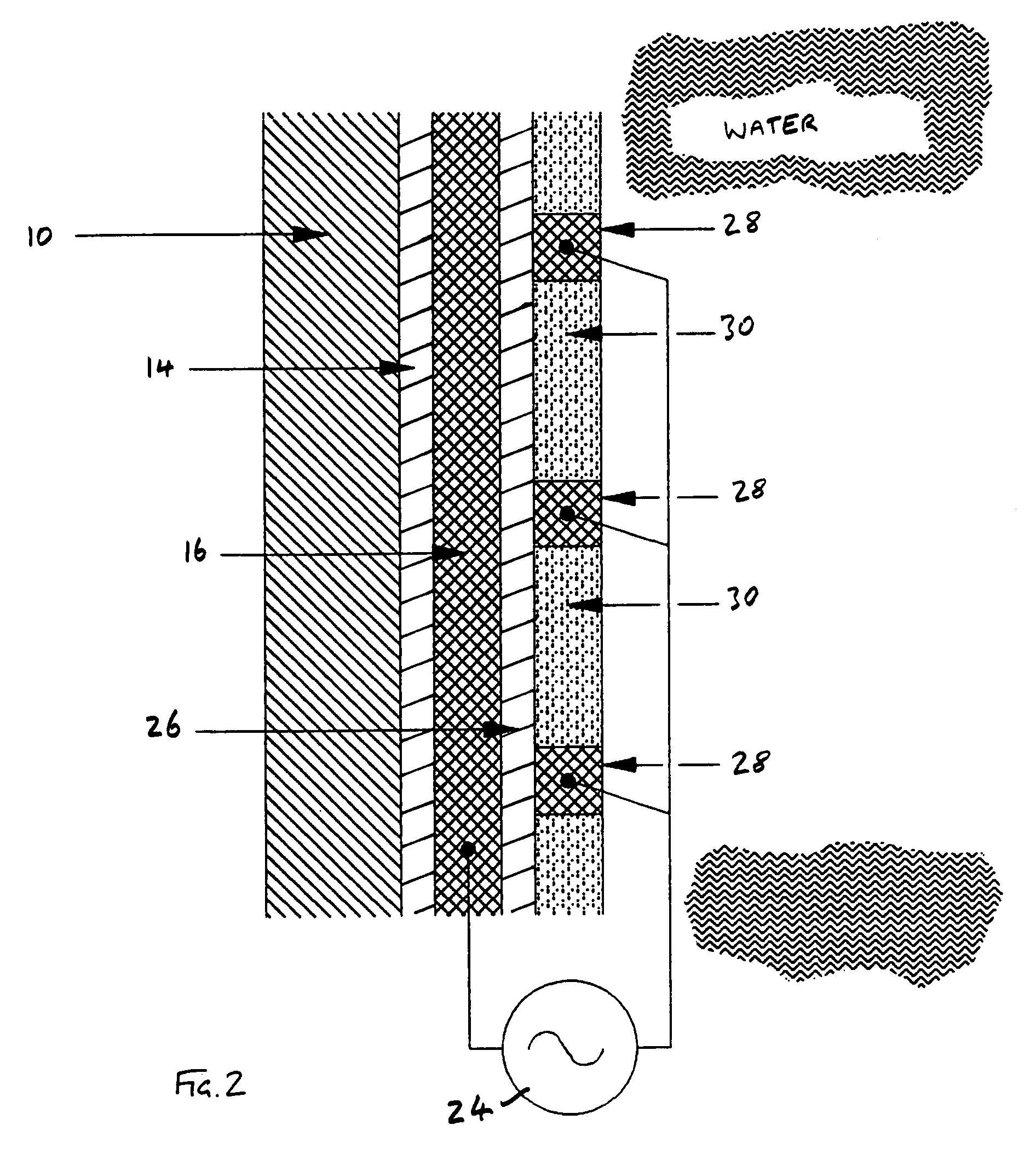
[0009]In either case, one of the conductors may define apertures therein. The conductor may take any suitable form and in a preferred embodiment, one of the conductors comprises a grid. The apertures in the grid may be of any suitable size dependent on the power of the power source used and may typically be 3 to 6 mm where the apparatus is for use in fresh water or 50 to 100 mm where the apparatus is for use in sea water. The electric field provided by a structure of this kind is particularly effective. Material may be provided in the said apertures to reduce water resistance, for example, and also reduce the surface area of the apparatus. Insulating material may be provided in the said apertures and / or, non-toxic, anti-fouling paint may be provided in the apertures.
[0012]The power source may be arranged to apply a potential across the conductors of preferably at least 3 kV. The frequency of the power source is preferably at least 300 Hz. The AC power source preferably outputs a substantially square wave signal. In this way the transition from positive to negative potential is achieved quickly and so the induced polarization within a larva, for example, will also change quickly increasing the effectiveness of the apparatus. Preferably, the duration of the transition stage of the AC cycle is less than 500 micro seconds.

Problems solved by technology

In this way, the two conductors can simply be mounted on the dielectric member and close spacing need not be achieved.

Method used


Image

  • Apparatus for harming or killing fouling flora or fauna and an item carrying the same
  • Apparatus for harming or killing fouling flora or fauna and an item carrying the same
  • Apparatus for harming or killing fouling flora or fauna and an item carrying the same

Examples


Embodiment Construction

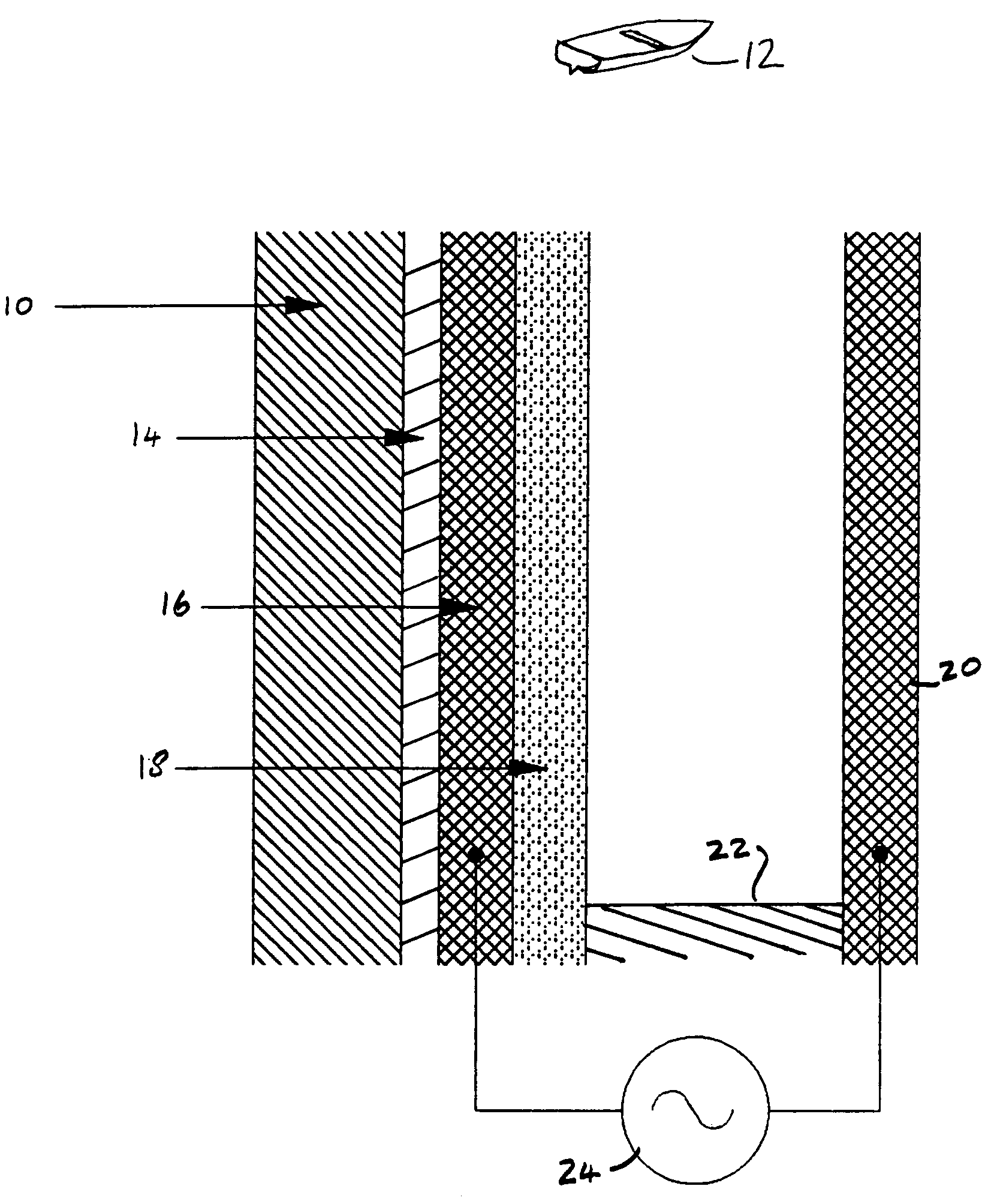
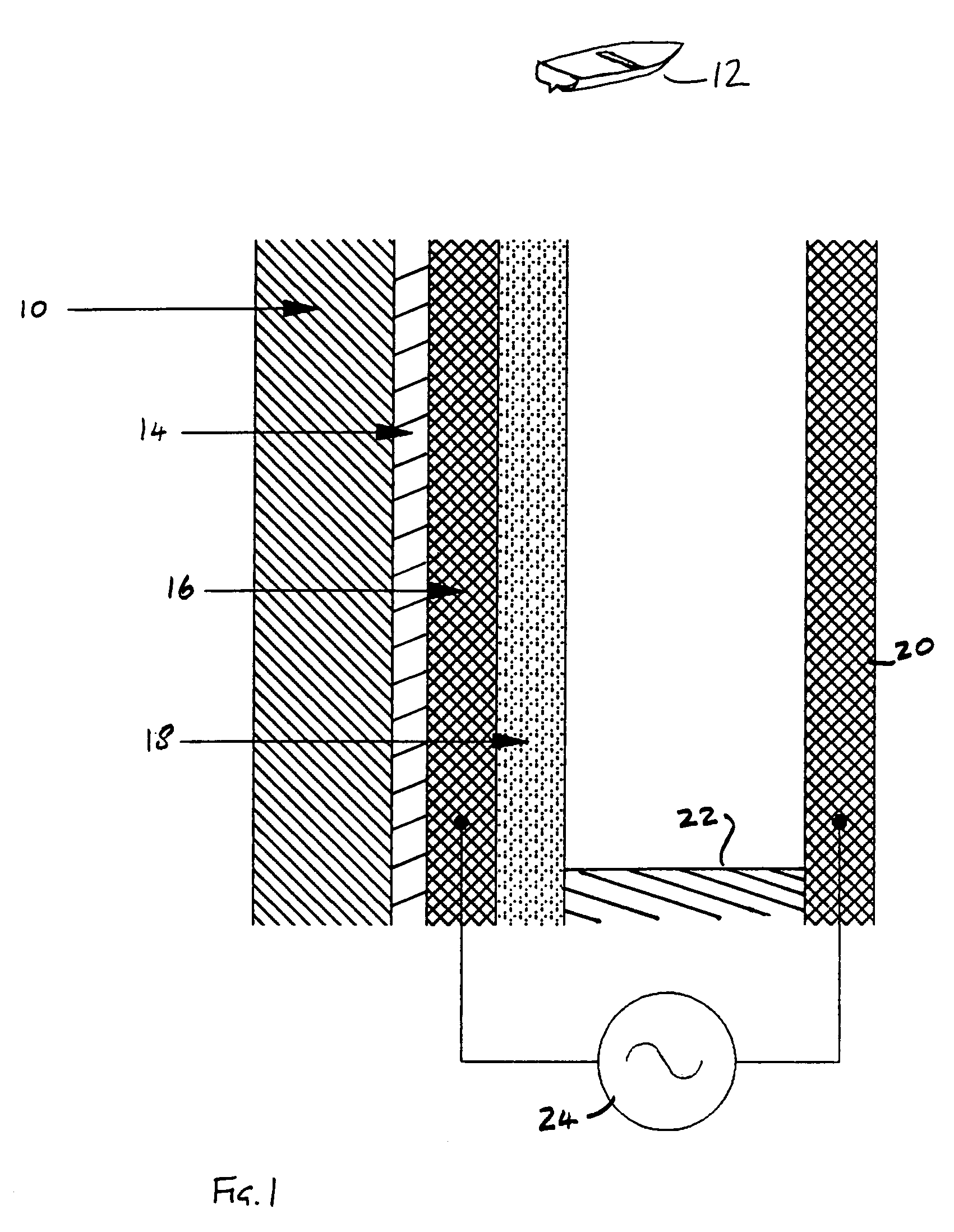
[0019]FIG. 1 shows part of the hull 10 of a boat 12 which is shown in inset. An insulating coating 14 is applied to the hull 10 and a conductive coating 16 is applied to the insulating coating 14. A further insulating coating 18 incorporating anti-fouling paint is applied to the conductive coating 16. A bare electrode 20 is provided spaced from the surface of the outer insulating coating 18 by a distance of about 3 mm. A plurality of insulating spacers 22, one of which is shown in FIG. 1, mount the electrode 20. The electrode 20 and the conductive coating 16 constitute the aforesaid conductors and each is wired to an AC power source 24 which has a 300 Hz, 3 kV, square wave AC output.

[0020]In use, with the AC power source operating, the oscillations in the electric field produced between the conductive coating 16 and the electrode 20 will be sufficient to disable or kill Daphnia larvae in over 80% of cases and, with the use of a 4.8 Kv source, a success rate of 95%–100% was obtained....


PUM


Abstract

Apparatus for harming or killing fouling flora or fauna, for example on boat hulls, comprises two conductors and an AC power source. The first conductor is a conductive coating while the second conductor is a spaced sheet in one embodiment and a grid on a dielectric insulating coating in another embodiment.

Description

BACKGROUND OF THE INVENTION[0001]The invention relates to apparatus for harming or killing fouling flora or fauna and an item carrying the same.[0002]Fouling of items placed in the water, such as boat hulls, is a well known problem. The fouling problem is usually combated by the use of a toxic, anti-fouling paint which should kill animal or plant life which attaches itself to the painted surface. The use of toxins in this way is environmentally undesirable and other methods of control or elimination of fouling have been investigated. One such method is described in International patent application no. WO92 / 17061 in the name of the present applicant. The disclosure of that prior document is incorporated herein by reference. WO92 / 17061 discloses a trap for swimming larvae such as the larvae of fresh water mussels. The trap comprises two metal plates which are coated with insulating material and spaced apart in fresh water. The plates are connected to a high voltage AC generator to pro...

Claims


Application Information

Patent Timeline
Patent Type & Authority Patents(United States)
IPC IPC(8): A01M19/00
CPCB63B59/04A01M21/046
Inventor OSTLIE, LARS STEINAR
Owner OCEAN ENVIRONMENTAL TECH
Learn More