
Polymeric roof rail

a polymer and composite technology, applied in the direction of roofs, mechanical equipment, transportation and packaging, etc., can solve the problems of heavy and/or expensive roof rails, and achieve the effect of improving strength to weight functionality, simple manufacturing of composite roof rails, and facilitating the contouring of exterior shapes

Inactive Publication Date: 2006-09-26
SPECIALTY VEHICLE ACQUISITION
View PDF18 Cites 3 Cited by
  • Summary
  • Abstract
  • Description
  • Claims
  • Application Information

AI Technical Summary

Benefits of technology

This approach results in a lighter, less expensive roof rail with improved strength-to-weight functionality, simplifying construction and enabling universal connecting pieces for various vehicle applications, reducing production costs and assembly complexity.

Problems solved by technology

These roof rails can be heavy and / or expensive to make.

Method used


Image

  • Polymeric roof rail
  • Polymeric roof rail
  • Polymeric roof rail

Examples


Embodiment Construction

[0025]The following description of the preferred embodiments is merely exemplary in nature and is in no way intended to limit the invention, its application, or uses.

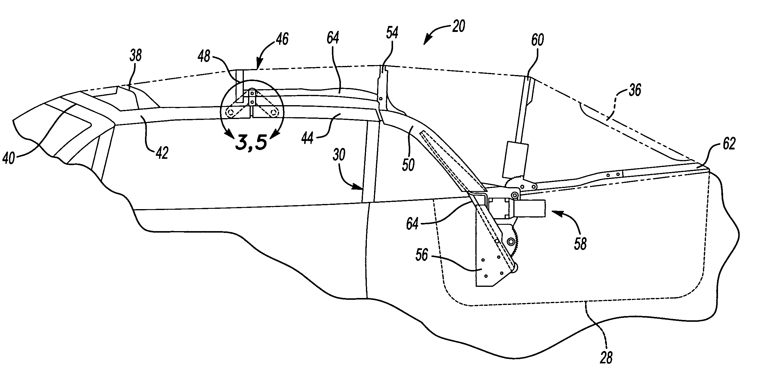
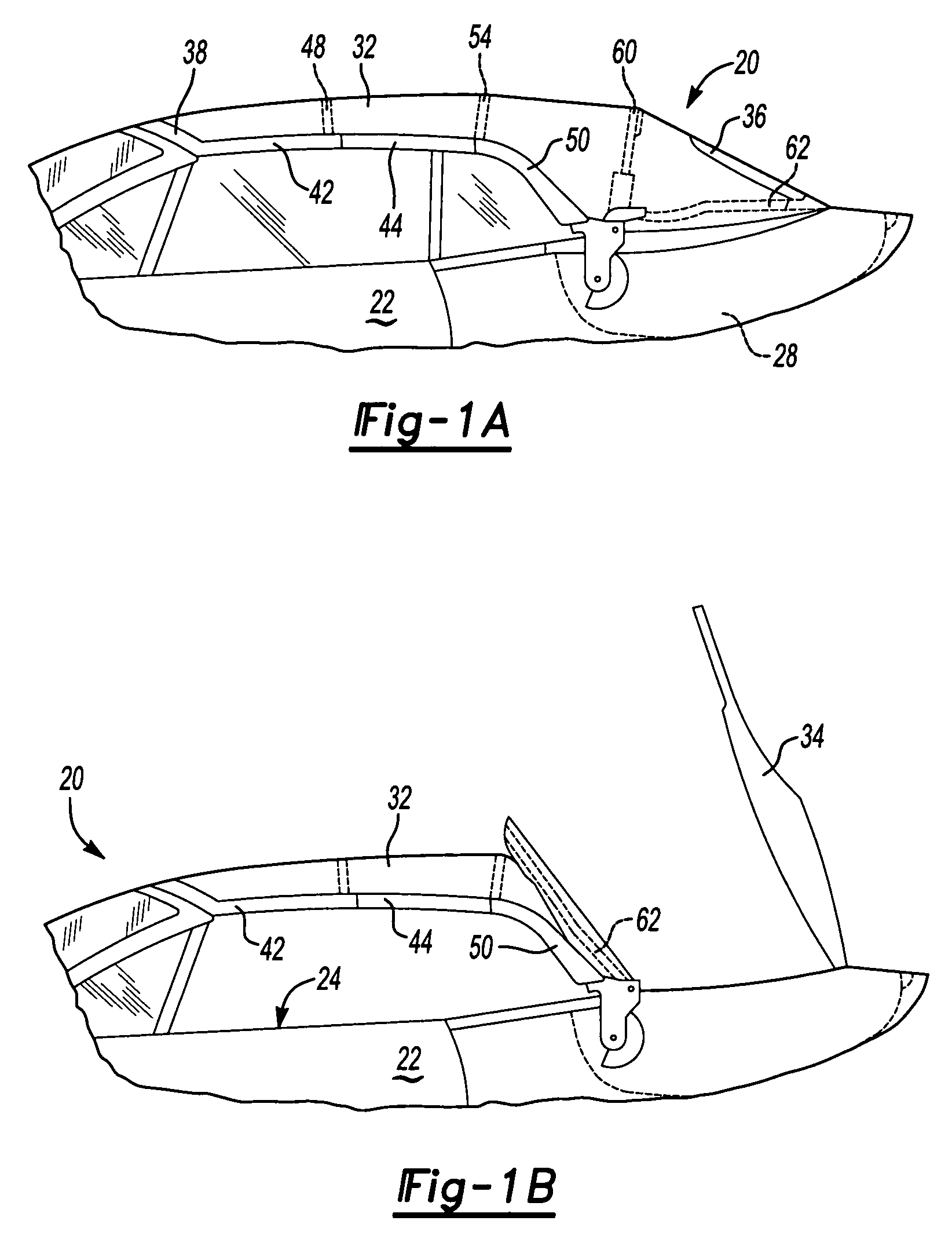
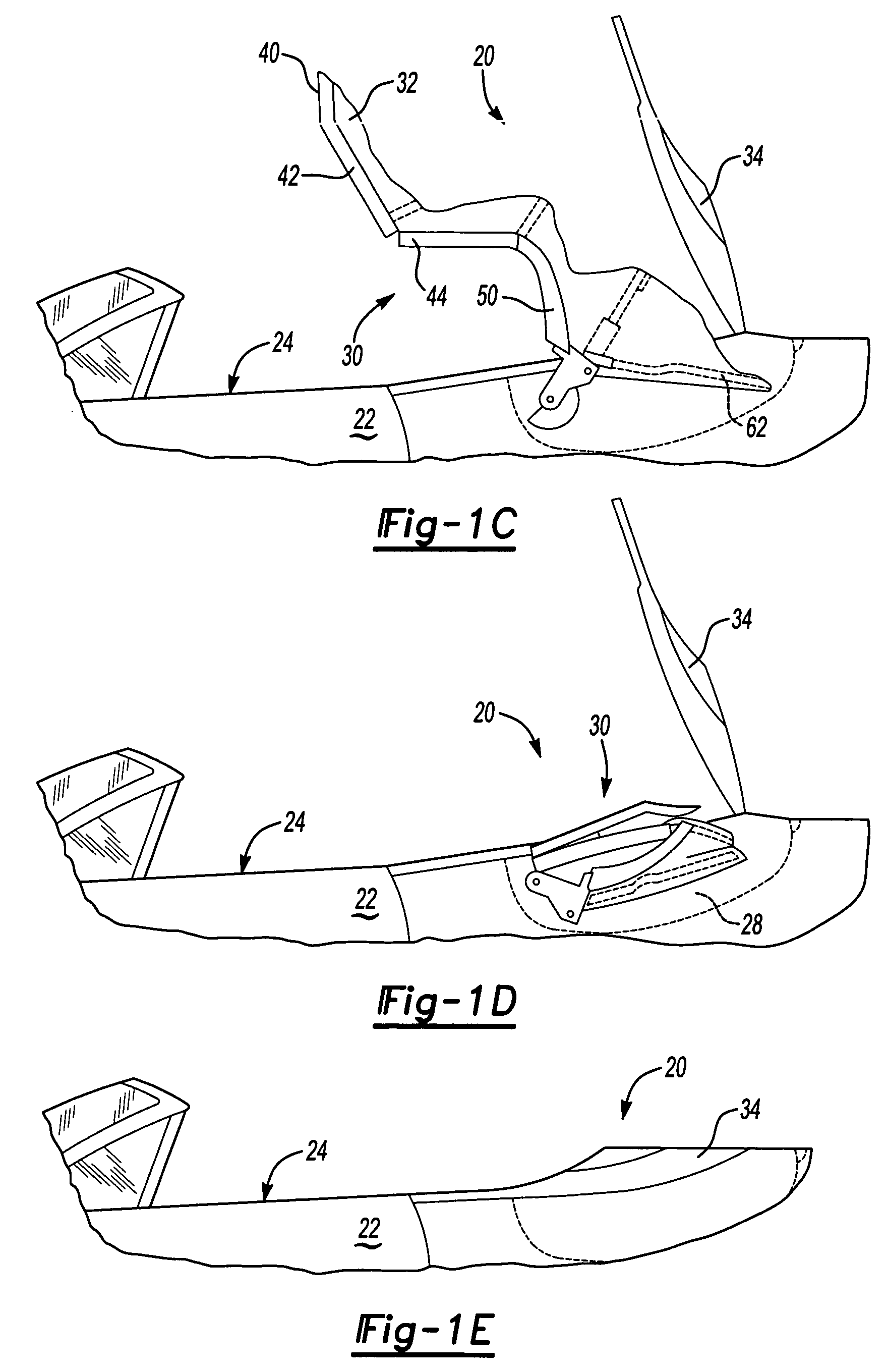
[0026]Referring to FIGS. 1A–E, a convertible roof system 20 according to the principles of the present invention is shown installed on an automotive vehicle 22 having a passenger compartment 24 and a stowage compartment 28. Convertible roof system 20 is the type utilizing a folding or top stack mechanism 30 that partially supports a roof cover 32 and is operable between a fully raised or extended position, as shown in FIG. 1A, through intermediate positions such as those shown in FIGS. 1B–D, and a fully stowed or retracted position within stowage compartment 28 beneath a tonneau cover 34, as shown in FIG. 1E.

[0027]Roof cover 32 includes a window or backlite 36 and is made from a pliable material, such as vinyl, canvas or a polyester fabric. If desired, roof cover 32 can also include a hard or rigid portion that optional...


PUM


Abstract

A convertible roof system uses composite roof rail(s). The composite roof rail can have portions that are made of differing materials. The composite roof rail can use universal connecting pieces for the ends of the roof rail. Adjacent composite roof rails can be formed about a connector that couples the adjacent roof rails together.

Description

BACKGROUND AND SUMMARY OF THF INVENTION[0001]This invention pertains generally to convertible roof systems for automotive vehicles and more specifically to a composite roof rail used in the convertible roof system.[0002]Traditional soft-top convertible roofs for automotive vehicles typically employ a top stack mechanism that is operable between extended (raised) and retracted (stowed) positions. The top stack mechanism typically employs three, four or five roof bows, having an inverted U-shape spanning transversely across the vehicle for supporting a vinyl, canvas or polyester fabric pliable roof cover. A number one roof bow is mounted to a pair of front roof rails and is typically latched to the stationary front header panel of the automotive vehicle body disposed above the front windshield. A number two bow is typically mounted to a pair of center roof rails which are pivotally connected to the front roof rails. Furthermore, the number three, four and any additional optional roof ...

Claims


Application Information

Patent Timeline
Patent Type & Authority Patents(United States)
IPC IPC(8): B60J7/00B60J7/12
CPCB60J7/1252
Inventor MACNEE, III, ARTHUR LGARSKA, BRADLEY R
Owner SPECIALTY VEHICLE ACQUISITION
Learn More