Device and method for automatically inspecting objects traveling in an essentially monolayer flow

a technology of automatic inspection and object flow, applied in the direction of measurement devices, material analysis through optical means, instruments, etc., to achieve the effect of simple and economical construction and us

Inactive Publication Date: 2006-09-26
PELLENC SELECTIVE TECH
View PDF12 Cites 17 Cited by
  • Summary
  • Abstract
  • Description
  • Claims
  • Application Information

AI Technical Summary

Benefits of technology

[0048]Thus, the main object of the present invention is to propose a machine and a method for inspecting and optionally sorting, which operates with a high through-put and for substantially single-layered flows of objects, this machine and this method being capable of discriminating reliably between objects having significant heights while being simple and economical to construct and use.

Problems solved by technology

However, these known machines all have fairly serious drawbacks and significant limitations.
However, these machines have a limited throughput and necessitate the presence of manual operators upstream of the machine to remove objects likely to disturb operation, in particular large sheets of plastic and large containers.
Therefore, they do not constitute a satisfactory solution for automation of sorting and have had little success.Planar flows, on the other hand, have proven themselves as this is exactly the presentation of objects found in manual sorting.
However, the sorting rate of this system is limited by the individual gripping of the sorted objects and does not exceed 60 to 100 kg / h per sorting module.
The only way to increase this rate is to cascade a plurality of identical sorting modules, and this increases the overall bulk of the machine and its cost.
However, this detection principle is too basic for complex cases: all objects have a degree of opacity, and it will be appreciated that multiple thicknesses of a material which is only slightly opaque (for example PET / polyethylene terephthalate) may not be distinguished from a single thickness of a more opaque different material (for example, PVC—polyvinyl chloride).
There is therefore the risk of ejecting all these sparingly opaque objects at once in error.
In addition, this system can only distinguish PVC from other plastics: it is incapable of distinguishing PET from HDPE (high density polyethylene) or PAN (polyacylonitrile).
Existing machines according to this document have limited efficacy and low outputs (proportions of desired objects from among the ejected objects): of 10 to 30%.
Finally, a significant drawback of the transmission assembly is that at least one of the two elements, the sensor or the transmitter, has to be below the flow.
There is therefore a risk of recurrent soiling or blockage of the lower element, necessitating repeated interventions at relatively short intervals.
The presence of a large-sized mirror of this type constitutes a fragile point of the overall structure, elongates the detection / ejection distance, increases the overall bulk of the detection station and is likely to lead to distortion and introduce inhomogeneities in the light flux recovered for analysis, leading to errors of detection.
The detection algorithm has to carry out two-dimensional reconstitution of the objects to be sorted before proceeding to eject them, and this necessitates a relatively large distance between the detection zone and the ejection zone, increasing the risks of erroneous ejection owing to a movement of the objects between detection and ejection.
Such a power would not be realistic (cost, energy consumption, heating).
However, this solution also has several drawbacks:it necessitates additional material, namely a vision system;it is dependent on the selection by vision of the point of spectrometric measurement on the object, and this may be awkward in the presence of labels or soiling;it is dependent on the immobility of the object on the mat: as the two detections are made on zones of about 1 m×1 m, the object moves by at least 1 m between its detection by vision and its detection by spectrometry, then by 0.5 m on average between its detection by spectrometry and its final ejection.
Immobility is never ensured when the conveyor advances at 2.5 m / s, particularly if the objects are bottles which are likely to roll.
The machine described in this document is obviously more flexible but more expensive and much less effective than the previous one.
A surface of this type gathers little light and limits the speed of analysis to 200 measurements per second.
Therefore, a spectrometer of this type cannot analyse all the points of a high-speed conveyor with the above-mentioned speeds and resolutions.
According to the inventor, the cost of a spectrometer would be minimised by microsystem production techniques, but the necessary resolution involves 25 to 50 spectrometers on the line to cover the width of the conveyor mat: the total cost, like the maintenance constraints, are therefore very high.
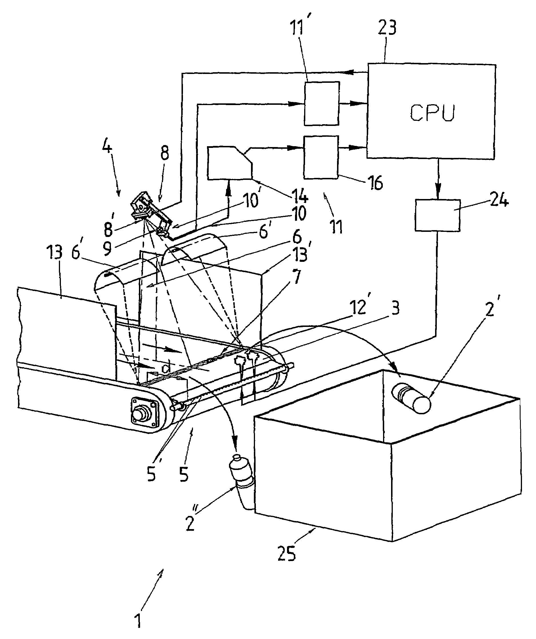
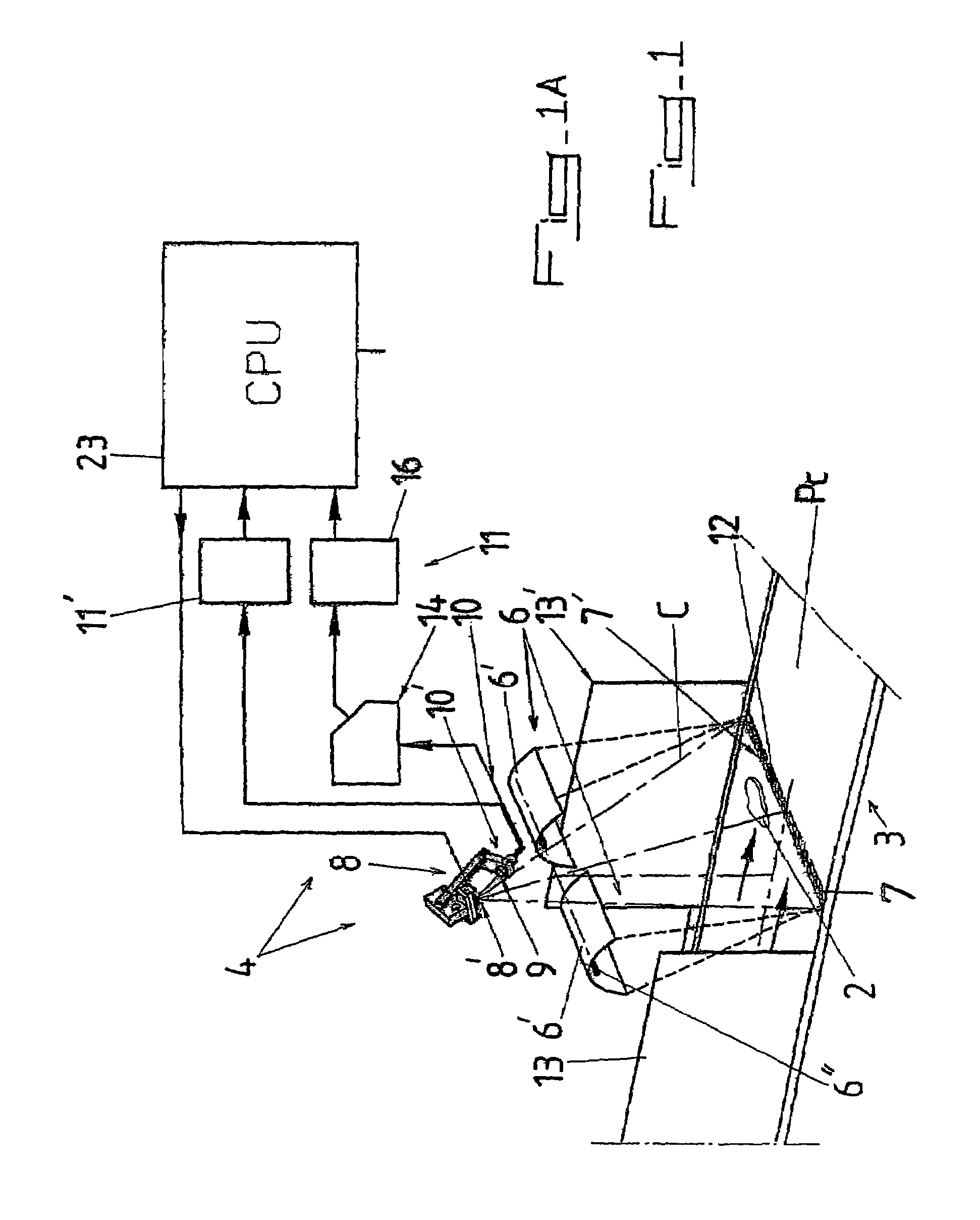
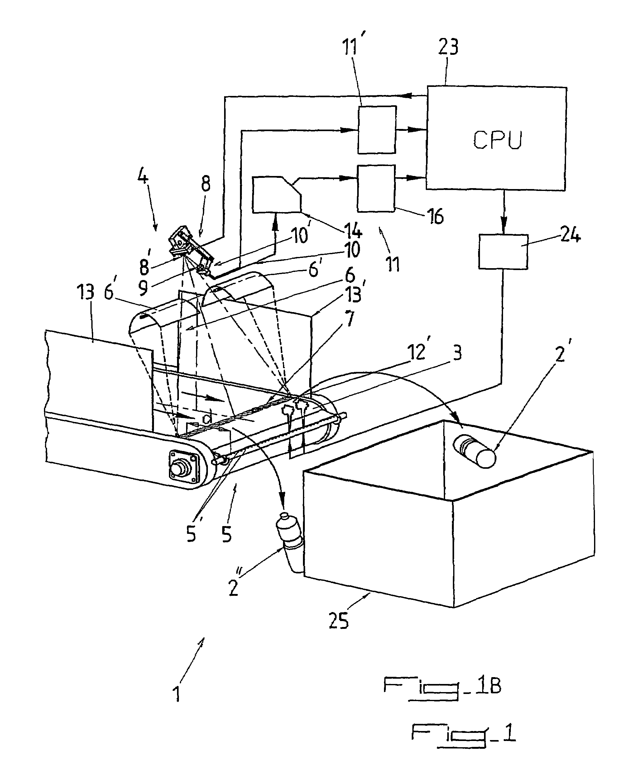
In addition to the drawbacks and limitations inherent in each of the above-mentioned devices and methods, one major drawback which is common to all these devices and methods should be mentioned, namely their inability to reliably process objects having a significant height, for example of about 10 to 30 cm, owing to the inadequate intensity of applied radiation at this distance from the plane of conveyance Pc of the travelling objects, or owing to the inability to recover the radiation to be analysed or else for both the aforementioned reasons.

Method used


Image

  • Device and method for automatically inspecting objects traveling in an essentially monolayer flow
  • Device and method for automatically inspecting objects traveling in an essentially monolayer flow
  • Device and method for automatically inspecting objects traveling in an essentially monolayer flow

Examples


Embodiment Construction

[0102]As shown in the figures of the accompanying drawings, and more particularly FIGS. 1 to 4, the machine for automatically inspecting objects 2 comprises at least one detection station 4 through or beneath which the flow of objects 2 passes, this detection station 4 comprising, in particular:[0103]means 6 for applying electromagnetic radiation in the direction of the plane of conveyance Pc of the conveyor 3, emitting said radiation so as to define a lighting plane Pe, the intersection of said lighting plane Pe and said plane of conveyance Pc defining a detection line 7 extending transversely to the direction of travel of the objects 2,[0104]a receiver device 8 periodically scanning each point on said detection line 7 and receiving radiation reflected by an elementary measuring zone 12 located in the region of the point scanned at this instant, the plane defined by said detection line 7 and the optical input centre 8″ of said device being known as the scanning plane Pb,[0105]means...


PUM

PropertyMeasurementUnit
wavelength rangesaaaaaaaaaa
lighting poweraaaaaaaaaa
areaaaaaaaaaaa

Abstract

A device and a method for automatically inspecting objects traveling in an essentially monolayer flow. The device comprises a detection unit through which the object flow passes, consisting of the following: elements for applying electromagnetic radiation in the direction of the plane of conveyance of the objects and defining a lighting plane, the intersection of the lighting plane and plane of conveyance defining a detection line; a receiver device periodically scanning each point on the detection line and receiving radiation reflected by an elementary measuring zone, the plane defined by the detection line and the optical input center being known as the scanning plane; elements for transmitting the reflected radiation. The radiation emitted is concentrated in the region of the lighting plane and the lighting plane and the scanning plane merge, whereupon the joint plane is inclined in relation to the normal of the plane of conveyance.

Description

BACKGROUND OF THE INVENTION[0001]The present invention relates to the characterisation and optionally the automatic sorting of objects, in particular recyclable domestic packagings, by their constituent materials and / or by their colour, the combination of a material or of a constituent substance and of a colour hereinafter being called a category.[0002]It relates to a device and a method for automatically inspecting travelling objects with characterisation and discrimination according to their chemical composition.[0003]The machine according to the invention is particularly but not exclusively suitable for inspection purposes and optionally for sorting, at high speed, various recyclable plastics packagings, in particular bottles made of PET, HDPE, PVC, PP and PS, as well as paper / cardboard, composite (drink packs) or metal packagings.[0004]However, this machine may also be used for inspecting and discriminating any other objects or articles containing organic chemical compounds and ...

Claims


Application Information

Patent Timeline
Patent Type & Authority Patents(United States)
IPC IPC(8): G01N21/00B07C5/342G01N21/35
CPCB07C5/342B07C5/368B07C5/3422
Inventor BOURELY, ANTOINEPELLENC, ROGER
Owner PELLENC SELECTIVE TECH
Why Eureka
Try Eureka