
Condition indicator for use by a conditional branch instruction

a condition indicator and conditional branch technology, applied in the field of data processing systems, can solve problems such as the inability to accurately predict the jump and the disassembly of the jump instruction, and achieve the effect of improving the system performan

Inactive Publication Date: 2006-09-26
UNISYS CORP
View PDF19 Cites 8 Cited by
  • Summary
  • Abstract
  • Description
  • Claims
  • Application Information

AI Technical Summary

Benefits of technology

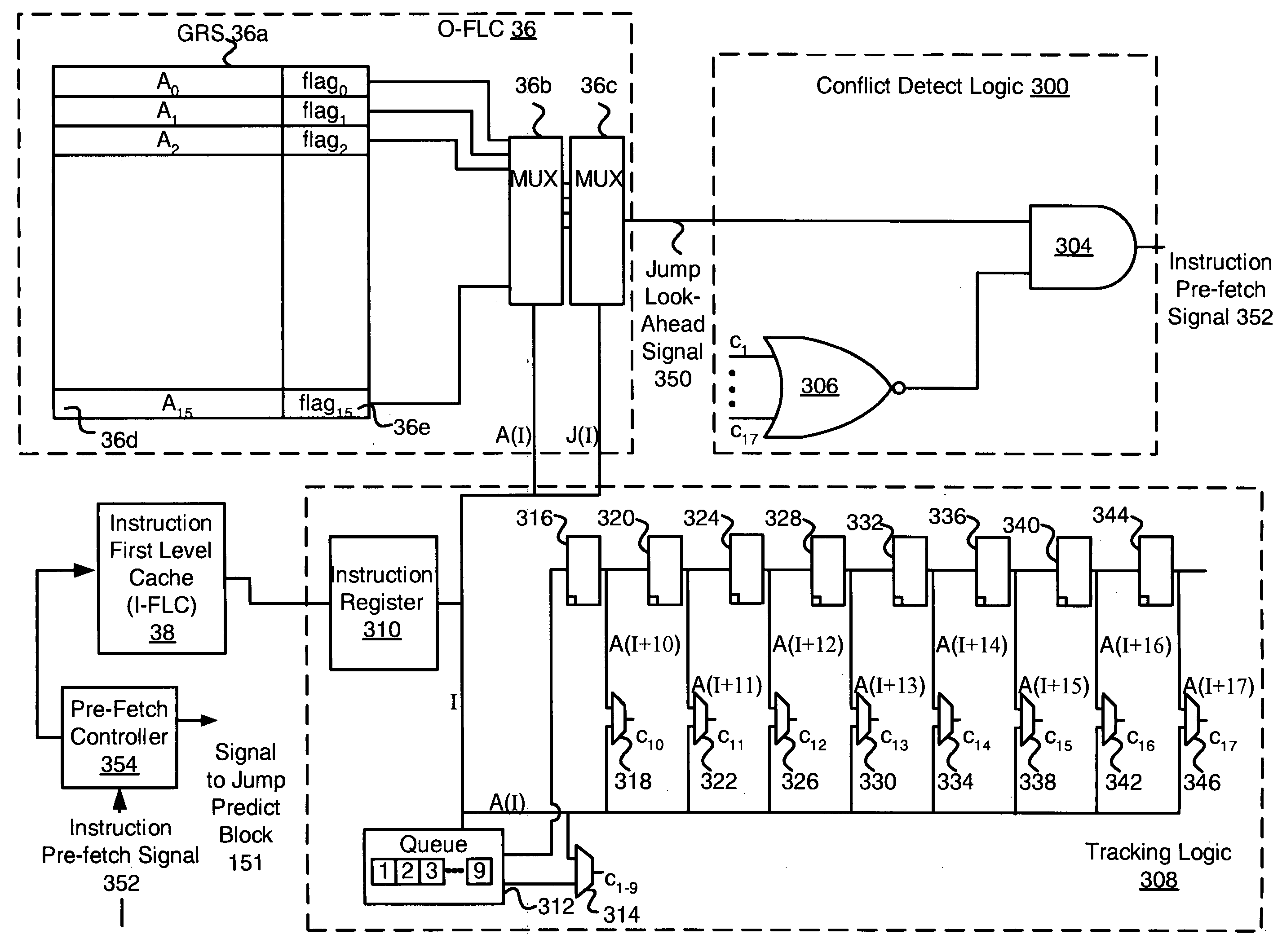
[0008]The present invention overcomes many of the disadvantages of the prior art by providing a branch prediction method and system that can accurately predict a branch condition early in the instruction pipeline, and preferably before the instruction reaches the arithmetic stage of the instruction processor. Thus, when the present branch prediction method is applied, the correct target instruction can be fetched early, thereby avoiding many of the inefficiencies associated with branch miss predictions.
[0011]In one illustrative embodiment, the conditional jump instruction reads the digital value from an addressed “A” register, which is part of a General Register Set (GRS). The particular “A” register is identified by an “A” address, which is provided by the instruction. To avoid misprediction, the present invention preferably checks to see whether any of the preceding instructions in the instruction pipeline also reference the addressed “A” register. If the addressed “A” register could be changed by a proceeding instruction in the instruction pipeline, the jump prediction may not be accurate and therefore may be disabled. If, however, none of the preceding instructions in the instruction pipeline reference the addressed “A” register, the status bits stored in the addressed “A” register are used to determine the condition of the current conditional jump instruction. By accurately predicting the jump condition early in the instruction pipeline, the proper instructions may be fetched and executed, which may significantly improve system performance.

Problems solved by technology

If the addressed “A” register could be changed by a proceeding instruction in the instruction pipeline, the jump prediction may not be accurate and therefore may be disabled.

Method used


Image

  • Condition indicator for use by a conditional branch instruction
  • Condition indicator for use by a conditional branch instruction
  • Condition indicator for use by a conditional branch instruction

Examples


Embodiment Construction

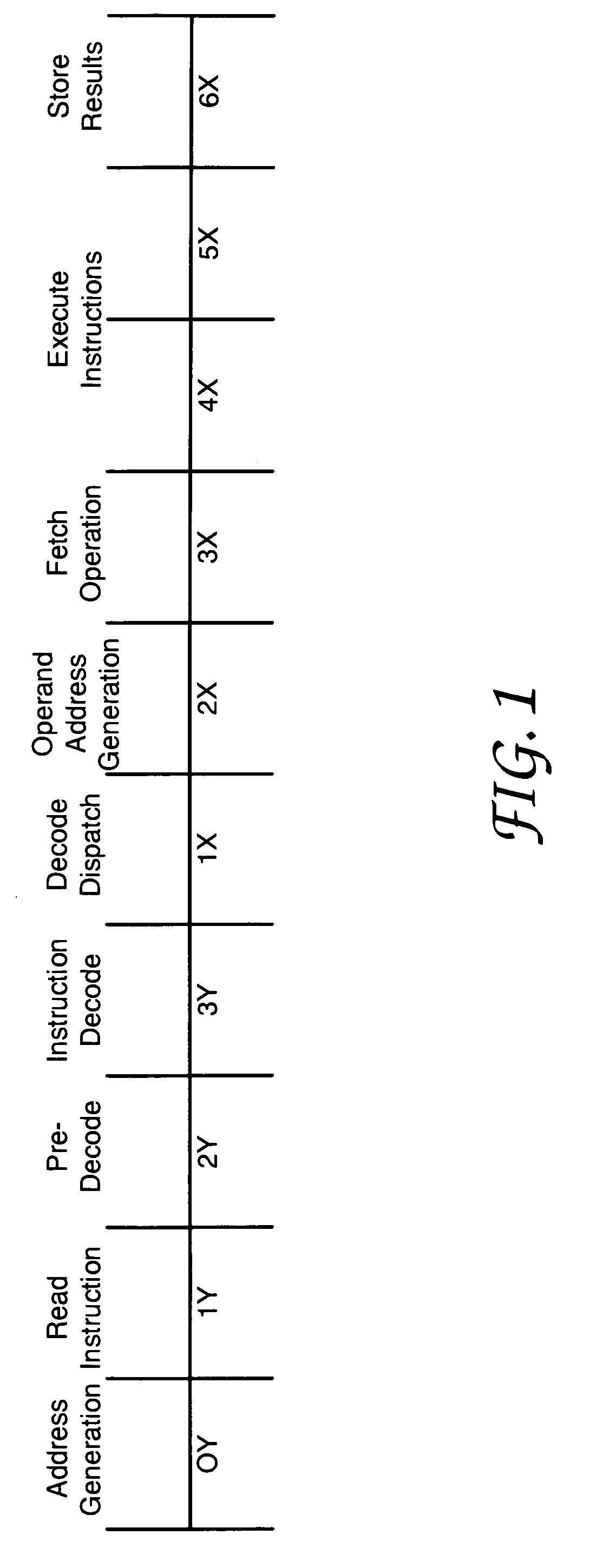
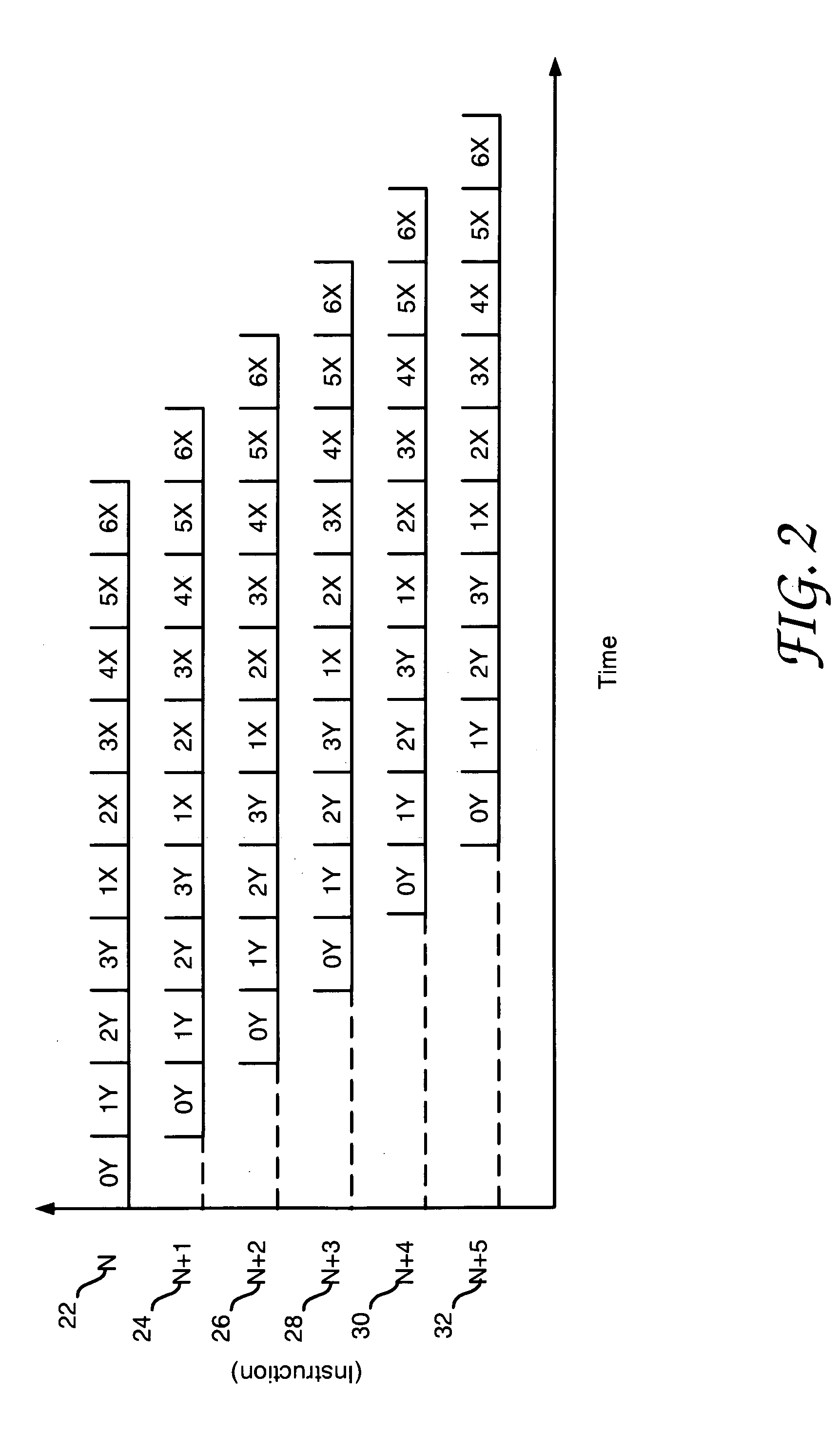
[0022]FIG. 1 is a timing diagram showing pipelined execution of an instruction by an exemplary Instruction Processor (IP). Pipelined instruction execution is a method of increasing system throughput by dividing the execution of each instruction into functional operations that can be performed within different areas of the IP. Since each functional area of the IP can be processing somewhat independently from the other functional areas, the IP can be executing portions of several instructions at one time so that instruction execution is overlapped.

[0023]The timing diagram of FIG. 1 shows a standard instruction being divided into ten functional operations. Each of these functional operations may be referred to as stage of execution. During the first stage, designated as the “0Y” stage, address generation occurs for the instruction. Next, the instruction is retrieved from cache memory during the “1Y” stage. Following instruction retrieval, pre-decode of the instruction begins during the...


PUM


Abstract

A branch prediction method and system are provided that accurately predict a branch condition early in an instruction pipeline of a data processing system. By accurately predicting the branch condition, the correct target instruction can be fetched early, thereby avoiding many of the inefficiencies associated with branch mispredictions. To accurately predict if a branch condition is satisfied, one or more pre-calculated status bits are stored along with a digital value that is read by the conditional branch instruction to determine if the branch condition is satisfied. By including such a status bit, the condition of the conditional branch instruction may be immediately determined, without waiting for the instruction to be processed by an arithmetic unit or the like in a subsequent pipeline stage.

Description

BACKGROUND OF THE INVENTION[0001]1. Technical Field of the Invention[0002]The present invention generally relates to the field of data processing systems, and more particularly to such systems that process instruction streams that include conditional branch instructions.[0003]2. Description of the Prior Art[0004]In most general purpose, stored program, digital computers, software is developed under the assumption that program instructions are executed in their entirety in a sequential fashion. This frees the software developer from the need to account for potential non-sequential operation of the hardware. However, most large-scale, modem machines are designed to take advantage of the overlapping of various functions. In its simplest form, such overlapping permits instruction processing of the N+1st instruction to be performed during operand processing of the Nth instruction. U.S. Pat. No. 4,890,225 issued to Ellis, Jr. et al. shows a rudimentary overlapped machine. To free the soft...

Claims


Application Information

Patent Timeline
IPC IPC(8): G06F9/44
CPCG06F9/30094G06F9/3873G06F9/3867G06F9/3844
Inventor FONTAINE, LAWRENCE RICHARDKUSLAK, JOHN STEVENLUCAS, GARY JOHNPELARSKI, MICHAEL DAVID
Owner UNISYS CORP
Learn More