Thermal isolation device for liquid fuel components

a technology of liquid fuel components and isolation devices, which is applied in the direction of machines/engines, mechanical equipment, lighting and heating apparatus, etc., to achieve the effects of reducing heat transfer, increasing thermal resistance, and increasing the operational performance of the components

Inactive Publication Date: 2006-10-03
GENERAL ELECTRIC CO
View PDF15 Cites 6 Cited by
  • Summary
  • Abstract
  • Description
  • Claims
  • Application Information

AI Technical Summary

Benefits of technology

[0003]This invention relates to a device that is designed to provide an increase in thermal resistance between the gas turbine liquid fuel system components and one of the primary heat sources, thus providing a reduction in heat transfer into the fuel component that leads to increased operational performance of those components.

Problems solved by technology

The plates are sized to be as large as possible so as to provide maximum surface area for cooling as well as to provide the maximum shielding of radiation heat loading from the end cover to the liquid fuel distributor valve, while being limited by geometric restrictions due to adjacent componentry on the current combustion end cover assembly and the limitations of additional structural concerns due to vibration.

Method used


Image

  • Thermal isolation device for liquid fuel components
  • Thermal isolation device for liquid fuel components
  • Thermal isolation device for liquid fuel components

Examples


Embodiment Construction

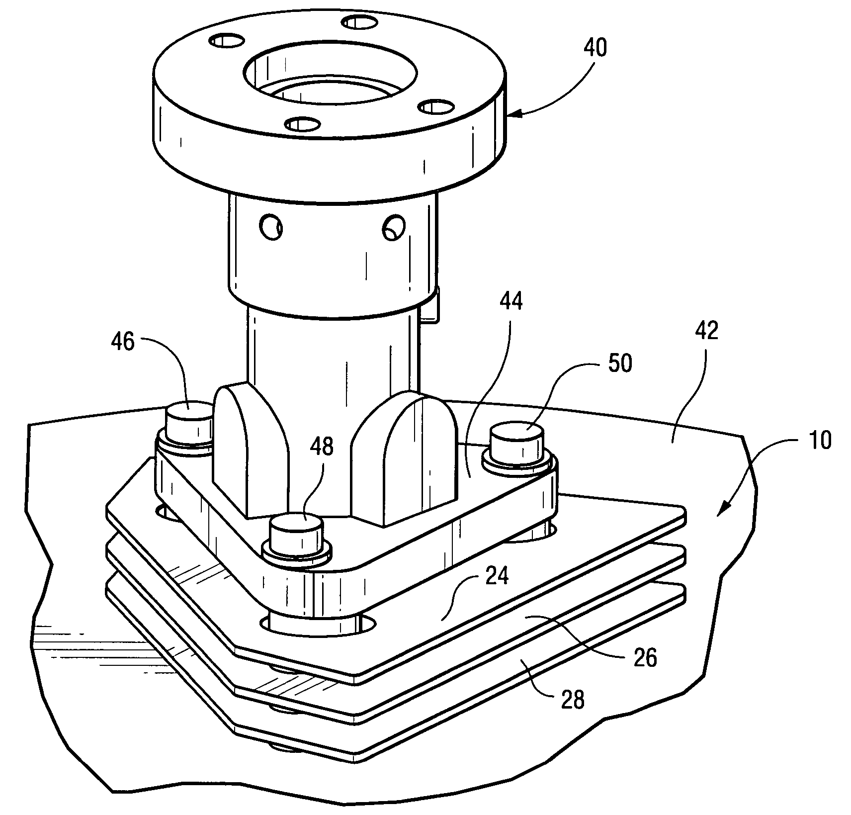
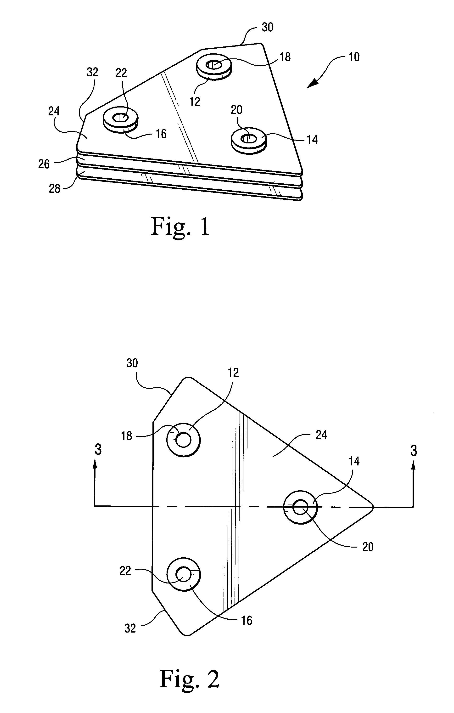
[0014]With reference initially to FIGS. 1–3, the thermal isolation device 10 is constructed of three discrete columns 12, 14 and 16, each formed with respective through holes (or bolt holes) 18, 20 and 22. A plurality of flat plates 24, 26 and 28 are secured to the columns in axially spaced relationship, i.e., axially spaced along the longitudinal axes of the columns.

[0015]The three cooling plates 24, 26 and 28 are approximately 0.100 inches in thickness, and their plan view geometry is approximately triangular, with truncated corners at 30, 32. The cooling plates 24, 26 and 28 generate a maximum footprint or coverage on the end cover, limited only by structural vibration concerns.

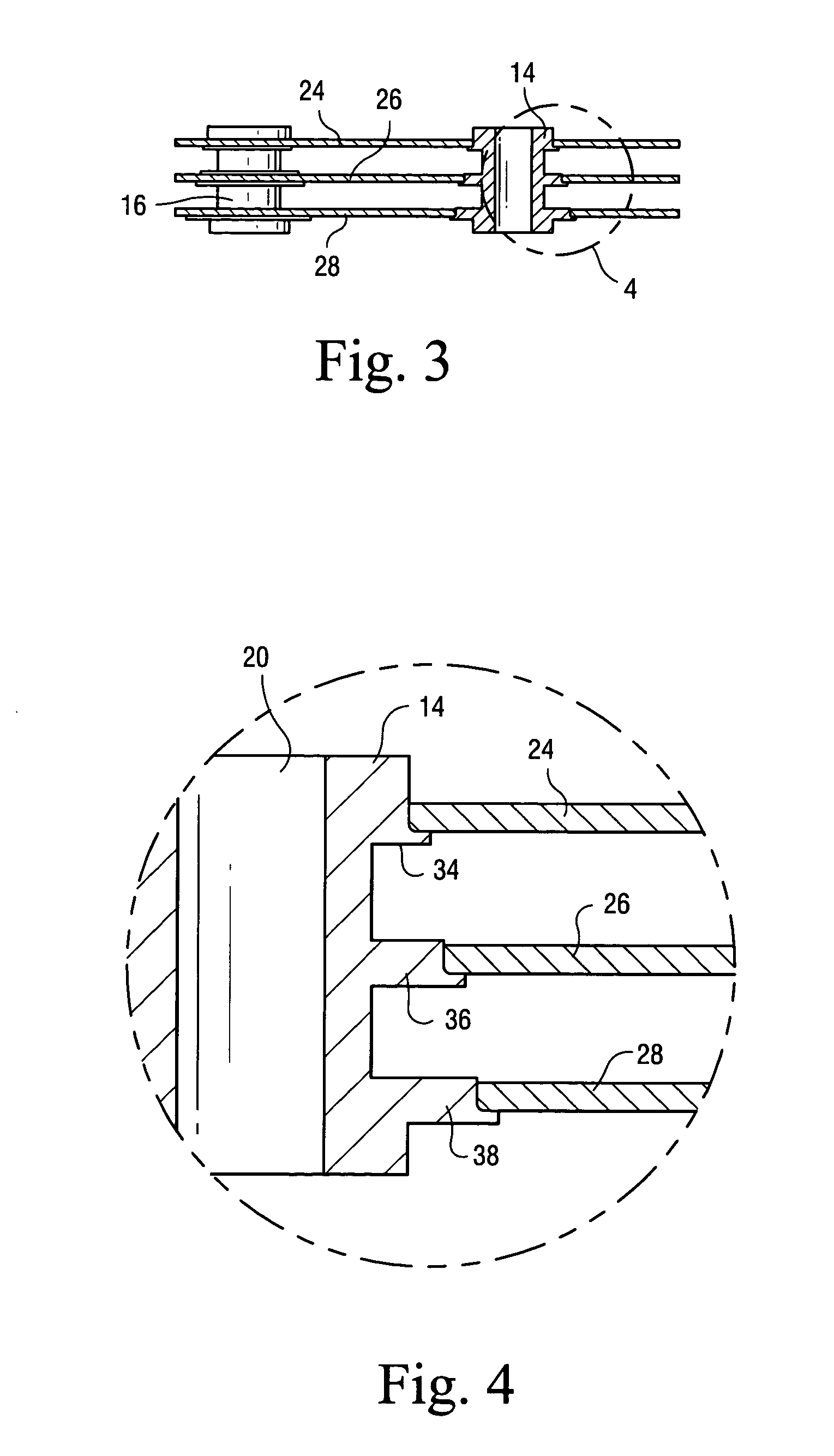
[0016]The plates 24, 26 and 28 are secured, by brazing for example, to respective radial flanges 34, 36 and 38, best seen in FIG. 4. The diameters of the flanges increase from top to bottom (in the orientation shown in FIGS. 3 and 4) facilitating brazing of the plates to the columns.

[0017]The length or hei...


PUM


Abstract

A thermal isolation device for a gas turbine combustor assembly includes a plurality of substantially flat plates secured in spaced relationship by a plurality of columns, at least one column incorporating a bolt hole for use in securing the device between a pair of combustor components.

Description

BACKGROUND OF THE INVENTION[0001]This invention relates to land based gas turbines used for power generation and, specifically, to a device that protects liquid fuel from convective, conductive and radiation heat transfer loads.[0002]It has been found that heat loading into the fuel components of the gas turbine engine are sufficient to form coke within the components, resulting in loss of turbine performance. The inventors are aware of no prior attempts to solve this problem.BRIEF DESCRIPTION OF THE INVENTION[0003]This invention relates to a device that is designed to provide an increase in thermal resistance between the gas turbine liquid fuel system components and one of the primary heat sources, thus providing a reduction in heat transfer into the fuel component that leads to increased operational performance of those components.[0004]In the exemplary embodiment, the thermal isolation device includes an assembly of three thin, flat cylindrical columns and three plates. The colum...

Claims


Application Information

Patent Timeline
Patent Type & Authority Patents(United States)
IPC IPC(8): F02G3/00F02C1/00F02C7/24F23R3/28
CPCF23R3/283
Inventor BELSOM, KEITH CLETUSSEAL, MICHAEL DAMIAN
Owner GENERAL ELECTRIC CO
Why Eureka
Try Eureka