
Apparatus and method for acquiring information while drilling

a technology for acquiring information and drilling equipment, applied in the field of acquisition of information, can solve the problems of consuming significant amounts of rig time, affecting the safety of drilling equipment, so as to reduce the likelihood of debris becoming trapped

Active Publication Date: 2006-10-03
SCHLUMBERGER TECH CORP
View PDF27 Cites 167 Cited by
  • Summary
  • Abstract
  • Description
  • Claims
  • Application Information

AI Technical Summary

Benefits of technology

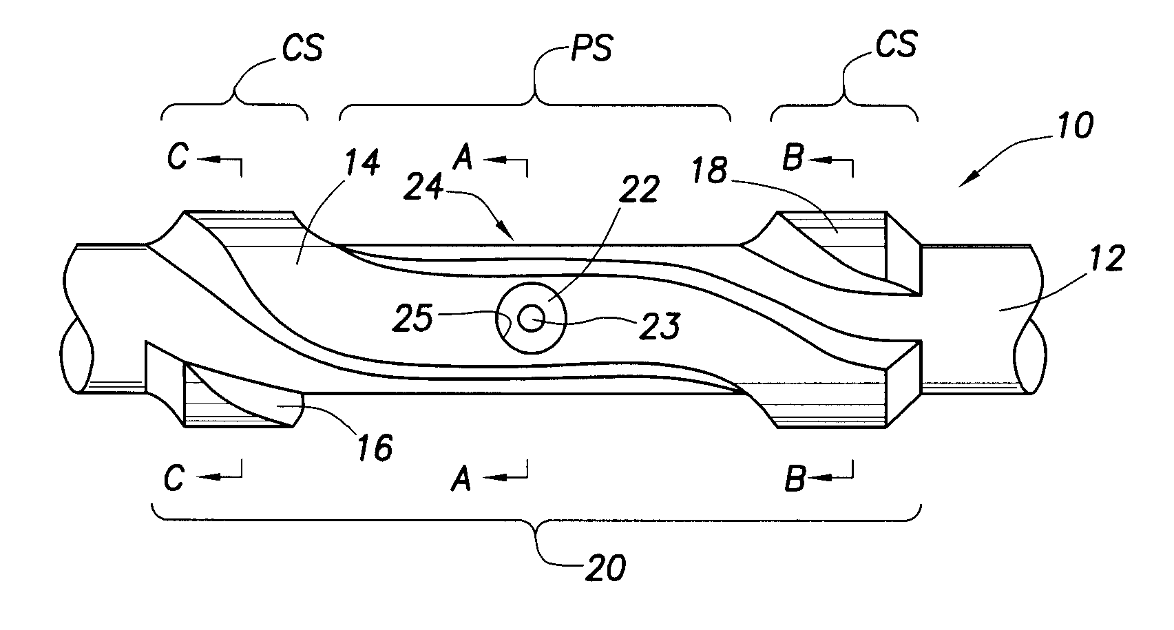
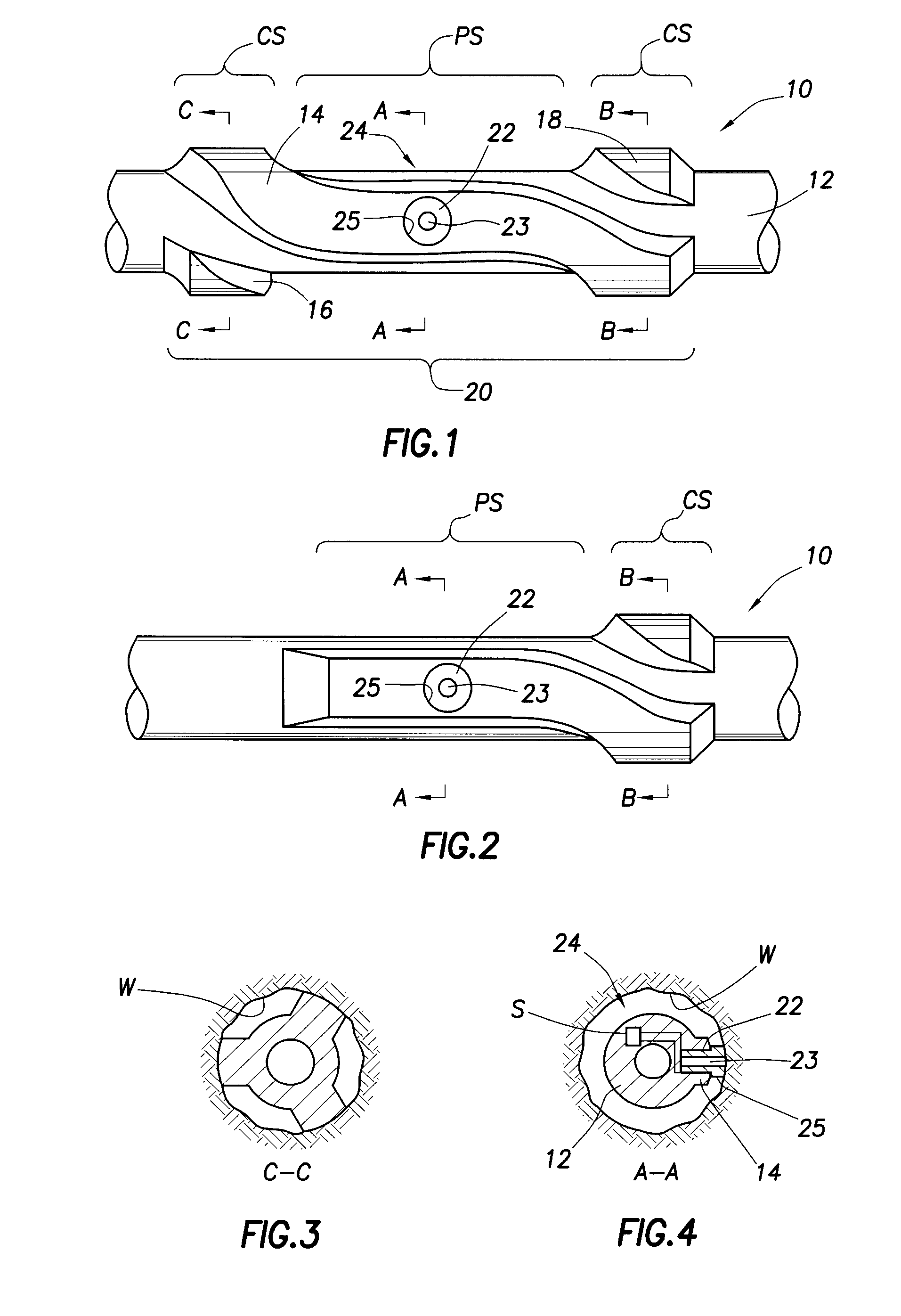
The present invention provides an apparatus for acquiring information from a subsurface formation penetrated by a wellbore. The apparatus includes a tubular body connected in the drill string and a probe at least partially carried within a channel formed in the body for movement between retracted and extended positions. The probe is designed to be recessed within the channel when retracted, allowing wellbore debris to flow along the channel away from the probe during drilling. The apparatus may also include a cover releasably-secured about the probe for protecting it while drilling. The actuator for moving the probe may be hydraulic fluid or electrical power. The apparatus may also include a backup support carried by the tubular body for assisting in engagement with the wellbore wall. The technical effects of the invention include improved accuracy and efficiency in acquiring information from subsurface formations and protection of the probe during drilling.

Problems solved by technology

Each of the aforementioned patents is therefore limited in that the formation testing tools described therein are only capable of acquiring formation data as long as the wireline tools are disposed in the wellbore and in physical contact with the formation zone of interest.
Since “tripping the well” to use such formation testers consumes significant amounts of expensive rig time, it is typically done under circumstances where the formation data is absolutely needed or it is done when tripping of the drill string is done for a drill bit change or for other reasons.
The section surrounding the probe, however, is typically not suitable for protecting the probe in its extended position against mechanical damage (cutting, debris, shocks to the wellbore wall, abrasion) and from erosion (from the fluids circulating in the annulus).
It is furthermore well known that the velocity of circulation fluids inside a wellbore has a direct effect on the thickness and integrity of the mud cake (the higher the velocity, the lower the sealing capabilities of the mud cake), which in turn will result in a local increase of the formation pressure near the wellbore wall (also called dynamic supercharging).
This effect typically reduces the accuracy of the formation pressure as measured by a probe on a tool.
Problems arise when there is a failure within the tool or the actuator extending and retracting these devices, leaving the tool deployed or set in the hole.
Often times, the retrieval of the tool under such circumstances will permanently damage the hydraulic pistons leaving the tool inoperable or worse, lead to hydraulic leak possibly causing the tool to flood with mud.

Method used


Image

  • Apparatus and method for acquiring information while drilling
  • Apparatus and method for acquiring information while drilling
  • Apparatus and method for acquiring information while drilling

Examples


Embodiment Construction

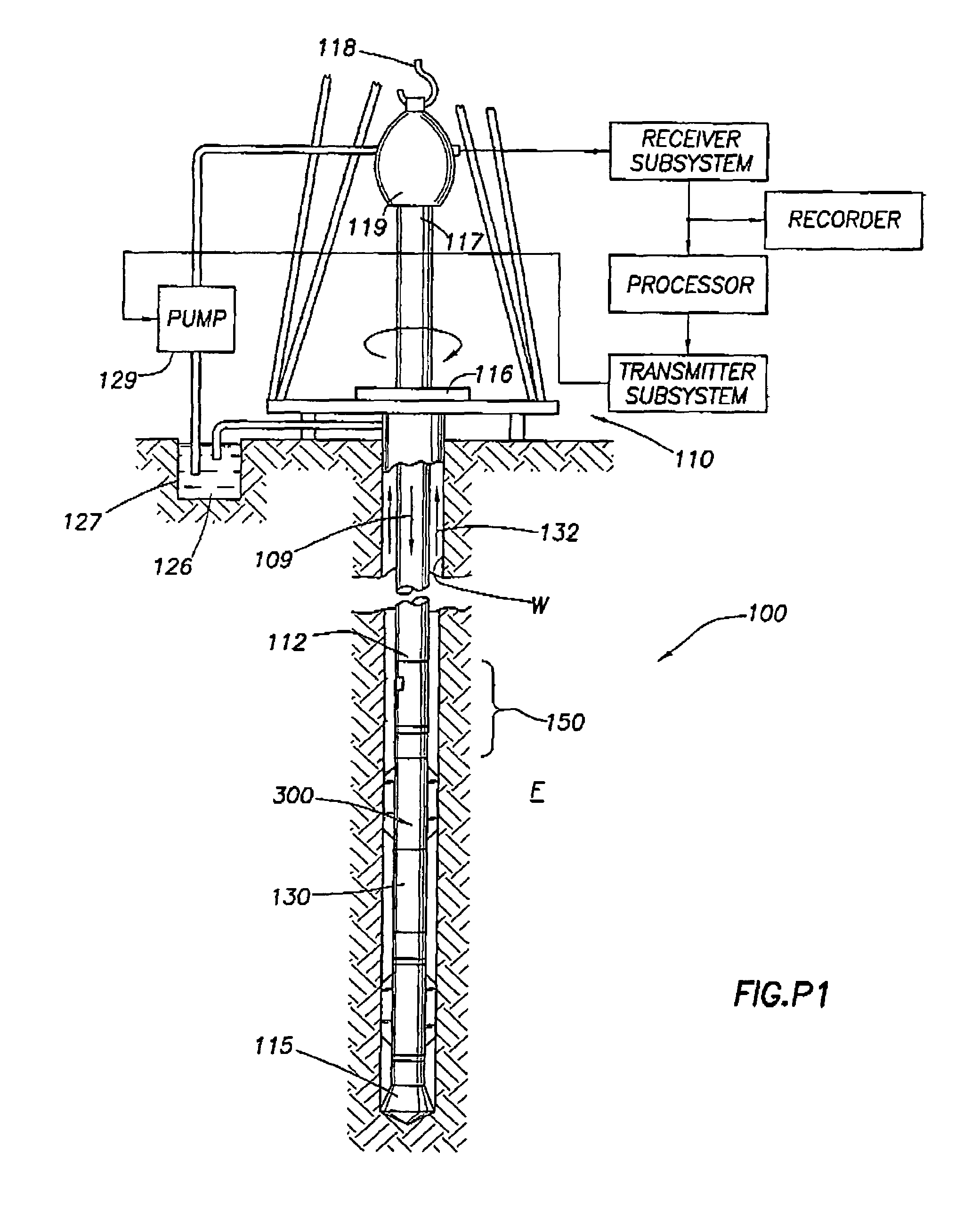
[0063]FIG. P1 illustrates a convention drilling rig and drill string in which the present invention can be utilized to advantage. A land-based platform and derrick assembly 110 are positioned over wellbore W penetrating subsurface formation F. In the illustrated embodiment, wellbore W is formed by rotary drilling in a manner that is well known. Those of ordinary skill in the art given the benefit of this disclosure will appreciate, however, that the present invention also finds application in directional drilling applications as well as rotary drilling, and is not limited to land-based rigs.

[0064]Drill string 112 is suspended within wellbore W and includes drill bit 115 at its lower end. Drill string 112 is rotated by rotary table 116, energized by means not shown, which engages kelly 117 at the upper end of the drill string. Drill string 112 is suspended from hook 118, attached to a traveling block (also not shown), through kelly 117 and rotary swivel 119 which permits rotation of ...


PUM


Abstract

An apparatus and method useful for acquiring information from a subsurface formation penetrated by a wellbore contemplate the use of a tubular body adapted for connection within a drill string disposed in the wellbore. The tubular body is equipped with one or more protuberances (e.g., ribs) defining an expanded axial portion. A probe is carried by the tubular body at or near a first location within the expanded axial portion of the body where the cross-sectional area of the expanded axial portion is a minimum. The probe is movable between retracted and extended positions. In another aspect, the inventive apparatus may further include a cover releasably-secured about the probe for protecting the probe while drilling. In a further aspect, the inventive apparatus may include a shearable backup support carried by the tubular body azimuthally opposite the probe permitting release of the apparatus from the wellbore in the event of a failure. In yet another aspect, the probe is at least partially carried within a debris-clearing channel formed in a protruding portion of the tubular body to promote free movement of the probe within the wellbore.

Description

BACKGROUND OF INVENTION[0001]1. Field of the Invention[0002]The present invention relates to the acquisition of information, such as pore pressure, from a subsurface formation while drilling. More particularly, the present invention relates to the stabilization and retrieval of apparatuses having utility for acquiring such information.[0003]2. Background of the Related Art[0004]Present day oil well operation and production involves continuous monitoring of various subsurface formation parameters. One aspect of standard formation evaluation is concerned with the parameters of reservoir pressure and the permeability of the reservoir rock formation. Continuous monitoring of parameters such as reservoir pressure and permeability indicate the formation pressure change over a period of time, and is essential to predict the production capacity and lifetime of a subsurface formation. Present day operations typically obtain these parameters through wireline logging via a “formation tester” t...

Claims


Application Information

Patent Timeline
Patent Type & Authority Patents(United States)
IPC IPC(8): E21B47/00E21B17/10E21B47/06E21B49/10
CPCE21B17/1078E21B47/01E21B49/10
Inventor FISSELER, PATRICKPALMER, TOMMATHER, JAMESLONGFIELD, COLINMEEHAN, RICHARDFOLLINI, JEAN-MARCHACHE, JEAN-MICHEL
Owner SCHLUMBERGER TECH CORP
Learn More