Method and apparatus for treating a layer of bulk material
a bulk material and treatment method technology, applied in lighting and heating apparatus, discharged material handling, furnace components, etc., can solve the problem of lack of vertical mixing movement in the material bed, and achieve the effect of improving heat recovery, preventing the edge region from flowing more quickly, and without energy loss or disruptive shaking
- Summary
- Abstract
- Description
- Claims
- Application Information
AI Technical Summary
Benefits of technology
Problems solved by technology
Method used
Image

Examples
Embodiment Construction
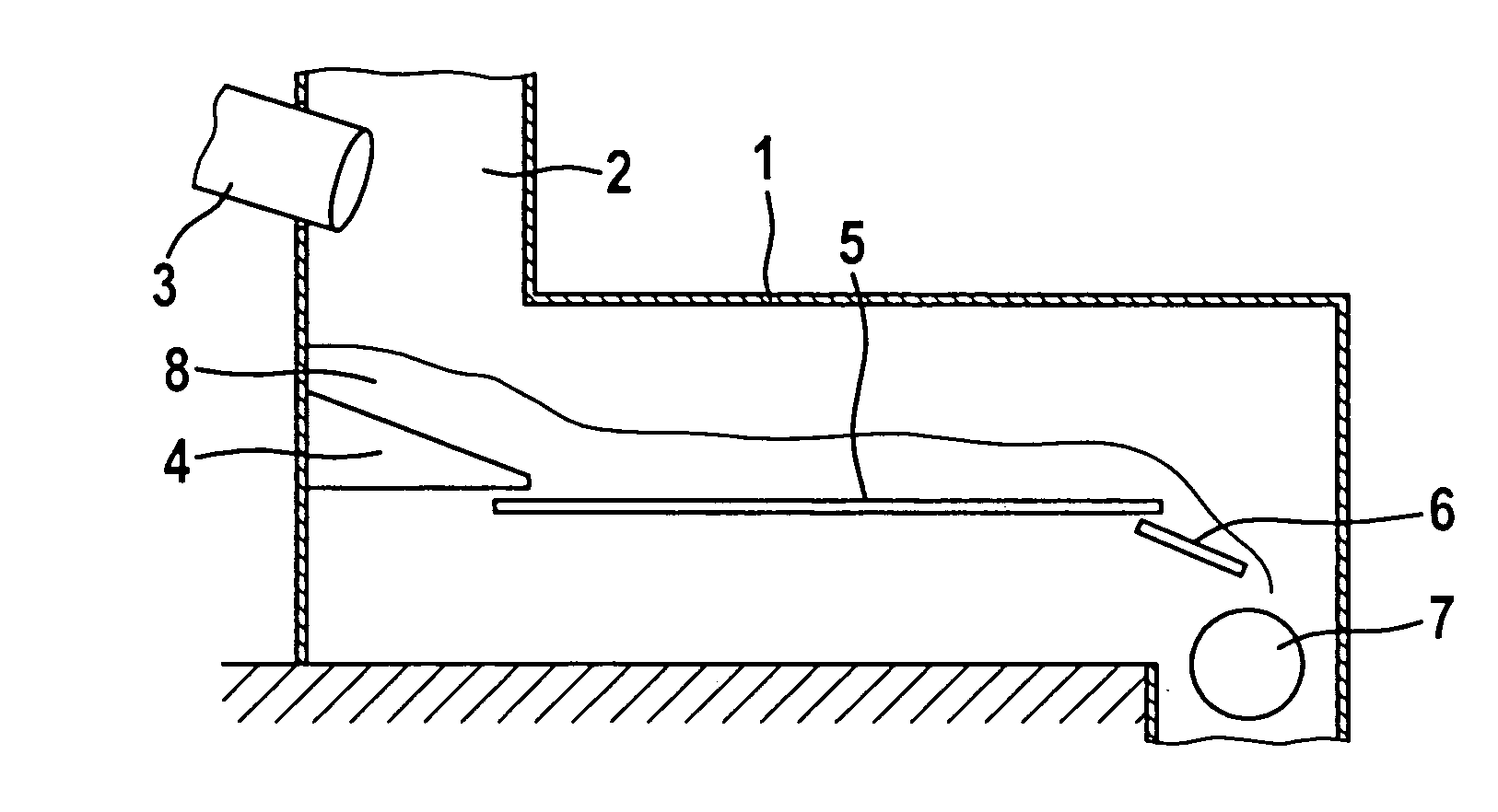
[0031]In accordance with FIG. 1, a cooler housing 1 forms a feed shaft 2 within which the end of a rotary tubular kiln 3 opens out. In the feed shaft 2, the material 8 drops onto a feed section 4 of the cooler, from where it passes onto the grate section 5 which is formed and operated in accordance with the invention. Where the following section, without any additional definitions, refers to the grate, this term is to be understood as meaning the grate section. The possibility of differently designed grate sections following or being connected upstream of this grate section should not be ruled out. The grate5 is arranged substantially horizontally. It can be arranged with a slight downward gradient, in order in this way to increase the resistance which prevents the material from following a grate plank as the latter moves back. On the other hand, this makes it easier for the material to move in the conveying direction and reduces the amount of energy required for the conveying. Howe...
PUM
 Abstract
Description
Claims
Application Information
 - R&D
- Intellectual Property
- Life Sciences
- Materials
- Tech Scout
- Unparalleled Data Quality
- Higher Quality Content
- 60% Fewer Hallucinations
Browse by: Latest US Patents, China's latest patents, Technical Efficacy Thesaurus, Application Domain, Technology Topic, Popular Technical Reports.
© 2025 PatSnap. All rights reserved.Legal|Privacy policy|Modern Slavery Act Transparency Statement|Sitemap|About US| Contact US: help@patsnap.com