Aerodynamic surfaced bicycle wheel

a bicycle wheel and surface technology, applied in the field of wheels, can solve problems such as greater drag, and achieve the effect of reducing aerodynamic drag on the wheel

Inactive Publication Date: 2006-10-03
COMPOSITECH
View PDF40 Cites 63 Cited by
  • Summary
  • Abstract
  • Description
  • Claims
  • Application Information

AI Technical Summary

Benefits of technology

[0011]In accordance with the present invention, a bicycle wheel includes a tire engaging portion located at the outward perimeter of the wheel, an inner portion located radially inward from the tire engaging portion, and a pair of air engaging side surfaces extending radially between the inner portion and the tire engaging portion forming the sides of the wheel. The air engaging side surfaces contain a plurality of surface features designed to create a turbulent boundary layer when the wheel travels through air to reduce aerodynamic drag on the wheel.
[0012]Drag is the air resistance that exerts itself in the direction opposite to the wheel's direction of movement, and thus the bicycle's direction of movement. As the wheel travels through the air, the air that surrounds the wheel has different velocities and thus, different pressures. The air exerts maximum pressure at a stagnation point on the front of the wheel. The air then flows around the side surfaces of the wheel with an increased velocity and reduced pressure. At some separation point, the air separates from the side surfaces of the wheel and generates a large turbulent flow area behind the wheel. This flow area, which is called the wake, has low pressure. The difference between the high pressure at the front of the wheel and the low pressure behind the wheel slows the wheel and the bicycle down. This is the primary source of drag for the bicycle wheel.
[0013]All objects moving through air have a thin layer, called the boundary layer, of air surrounding them. The object shapes range from blunt to streamlined. Blunt objects create large wakes behind them that in turn create greater drag. More streamlined objects create a smaller wake and therefore less drag. The surface features on the wheel cause a thin boundary layer of air adjacent to the wheel's outer surface to become turbulent. This turbulence energizes the boundary layer and helps keep it attached to the sides of the wheel longer, thus moving the separation point further backward on the wheel which reduces the size of the wake behind the wheel creating a more streamlined and aerodynamic air flow. As a result, there is a reduction in the area of the wake behind the wheel which increases the pressure behind the wheel, and substantially reduces the aerodynamic drag. It is the surface features on the wheel of the present invention that creates the turbulence in the boundary layer and reduces the aerodynamic drag.
[0016]One feature of the present invention is that it includes, on its air engaging surface, an array of surface features such as dimple-shaped depressions. The dimple-shaped depressions provide two advantages, with the first being aerodynamic, and the second being structural. With respect to the aerodynamic advantages, the covering of dimples on the air engaging surface creates a thin layer of air next to the wheel, the boundary layer. This boundary layer of air becomes turbulent in its flow patterns over the surface features of the air engaging surfaces. Rather than flowing in smooth continuous layers over the air engaging surface, the dimples cause the air to have a microscopic pattern of fluctuations and randomized flow. This “turbulence” in the boundary layer enables the air flowing around the air engaging surface to better follow the surface of the air engaging surface, and enables the air to travel further along the air engaging surfaces of the wheel. This creates a much smaller wake at the “down stream end” of the wheel. This reduced wake results in a significant reduction in the aerodynamic drag of the wheel.
[0017]The use of surface depressions, such as an array of dimpled depressions or radially extending depressions, can also provides structural advantages to the wheel, especially a disc-type wheel. A disc-type wheel generally includes an air engaging surface that extends continuously between the hub at the center of the wheel, and a tire-engaging portion at the radially outward perimeter of the wheel. As such, the first and second air engaging surfaces in prior wheels comprise smooth circular planes having a diameter that is usually in a range of 26 or 27 inches. Although the carbon fiber composite material from which disc wheels such as the ZIPP® 900 Disc Wheel are made is very rigid, it will be appreciated that any large planar body, such as a disc wheel, upon which radially and axially directed forces are exerted, may be induced to flex or bow. An array of surface features placed on the air engaging surfaces which protrude into and / or extend out of the major plane of the air engaging surfaces of a wheel can increase the rigidity of the wheel, and enhance the resistance of the wheel to flexing movements.

Problems solved by technology

This is the primary source of drag for the bicycle wheel.
Blunt objects create large wakes behind them that in turn create greater drag.

Method used


Image

  • Aerodynamic surfaced bicycle wheel
  • Aerodynamic surfaced bicycle wheel
  • Aerodynamic surfaced bicycle wheel

Examples


Embodiment Construction

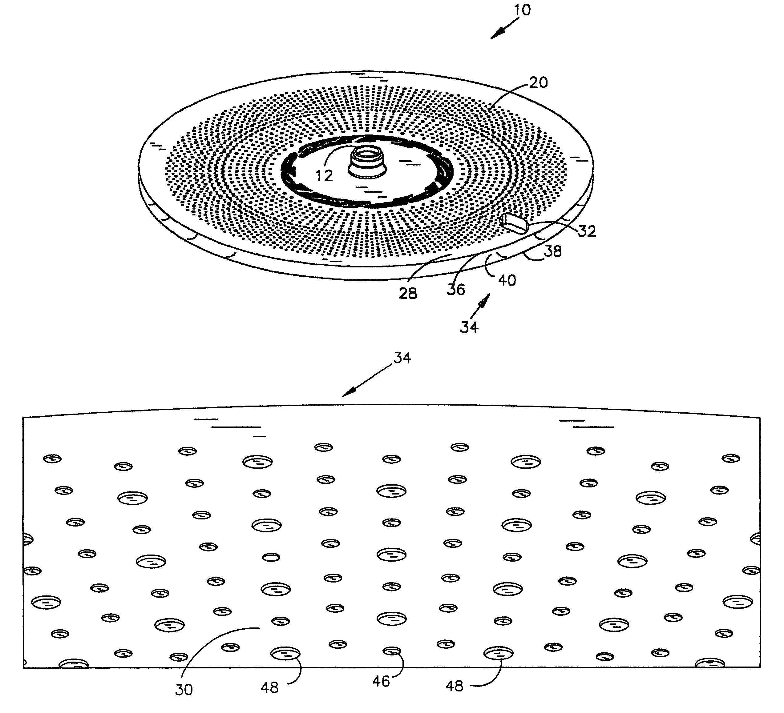
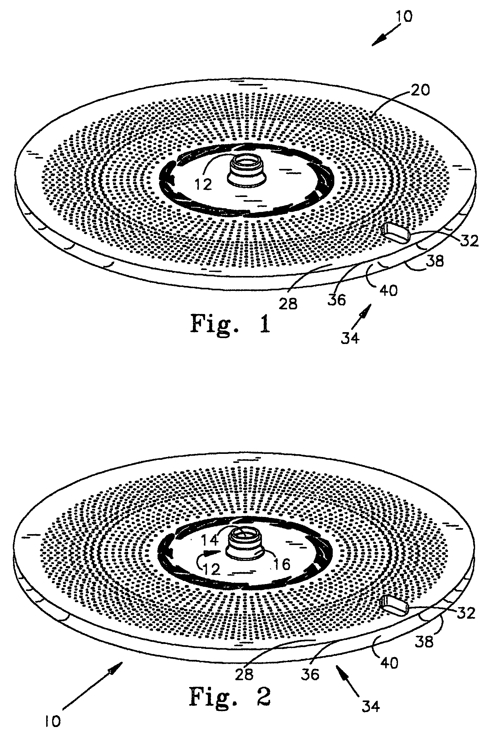
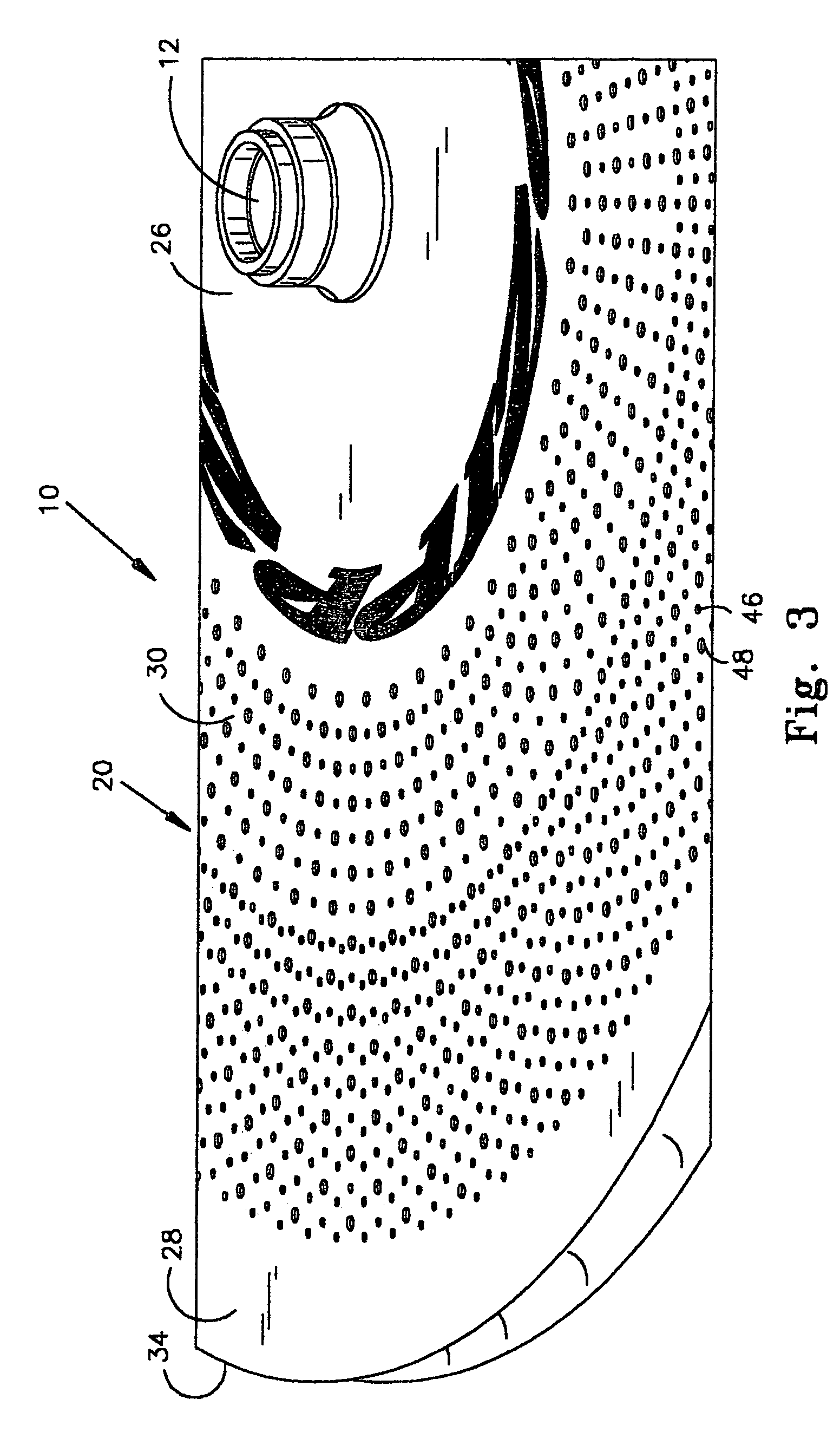
[0035]FIGS. 1–7 illustrate an embodiment of a disc type bicycle wheel 10 which is generally circular or disc-shaped, and includes a hub portion 26 with a hub 12 at its center, a tire engaging portion 34 at its radial perimeter, and first and second axially-opposed, air engaging surfaces 20, 22 extending from the hub portion 26 to the tire engaging portion 34.

[0036]The wheel 10 shown in the figures is composed primarily of a core that may either be hollow, filled with foam, or contain some foam and hollow spaces, such as in the honeycomb type core used by the Applicant. The core is overlain with a carbon fiber composite material which forms the first and second air engaging surfaces 20, 22. In this regard, the wheel 10 shown in FIGS. 1–7, has an exo-skeletal structure where the carbon fiber skin provides a majority of the wheels' shape and structural strength, with the interior core, if any, being used for a filler material to aid in the manufacture of the carbon fiber wheel 10. Addi...


PUM

PropertyMeasurementUnit
depthaaaaaaaaaa
depthaaaaaaaaaa
diameteraaaaaaaaaa

Abstract

A bicycle wheel includes a tire engaging portion located at the outward perimeter of the wheel, an inner portion located radially inward from the tire engaging portion A pair of air engaging side surfaces extend radially between the inner portion and the tire engaging portion forming the sides of the wheel. The air engaging side surfaces contain a plurality of surface features designed to create a turbulent boundary layer when the wheel travels through air to reduce aerodynamic drag on the wheel.

Description

REFERENCE TO RELATED APPLICATIONS[0001]This Application claims the benefit of Ording and Poertner U.S. Provisional Application No. 60 / 416,107, filed 04 Oct. 2002. and is co-pending with Ording and Poertner PCT Application Ser. No. PCT / US03 / 31669 filed concurrently herewith on 03 Oct. 2003.I. TECHNICAL FIELD OF THE INVENTION[0002]The present invention relates to a wheel, and more particularly to a bicycle wheel having an aerodynamically enhanced surface.II. BACKGROUND OF THE INVENTION[0003]The technology underlying the design of bicycle wheels has evolved in recent years. For many years, sturdiness and ease of manufacture were the primary driving forces underlying the design of a bicycle wheel. However, increasingly, bicycle wheels, and especially bicycle wheels designed for racing purposes, are being designed to be light-weight and aerodynamically efficient.[0004]A variety of techniques have been used to achieve lighter weights, with most of the design efforts being centered in the ...

Claims


Application Information

Patent Timeline
Patent Type & Authority Patents(United States)
IPC IPC(8): B60B3/10B60B5/02B62D35/00B64C1/38B60B3/08B60B7/00B60B19/00
CPCB60B3/007B60B3/082B60B3/085B60B3/10B60B5/02B60B7/0006B60B19/00B60B2360/10B60B2360/104B60B2360/3416B60Y2200/13
Inventor ORDING, ANDREWPOERTNER, JOSHUA R.
Owner COMPOSITECH
Why Eureka
Try Eureka