Catheter with spiral cut transition member

a transition member and catheter technology, applied in catheters, other medical devices, surgery, etc., can solve the problems of kinking at the joint, affecting the flexibility of the transition, and the hypertubing is often prone to kinking

Inactive Publication Date: 2006-10-03
BOSTON SCI SCIMED INC
View PDF195 Cites 43 Cited by
  • Summary
  • Abstract
  • Description
  • Claims
  • Application Information

AI Technical Summary

Benefits of technology

[0018]In a preferred embodiment, the transition member is secured to or proximate to the intermediate portion of the inner member and extends distally therefrom. To help secure the transition member to the inner member, the transition member may have a proximal portion sized so that the transition member can be friction fit over a portion of the tapered portion of the inner tube. An adhesive may also be used to secure the transition member to the intermediate portion of the inner tube. In a preferred embodiment adhesive is applied proximate the proximal end of the transition member only so that the transition member distal of the adhesive is free-floating. As discussed above, the transition member may engage at least part of the inner member and outer tube when the catheter is provided in a bent configuration.

Problems solved by technology

One limitation of such a construction is that hypotubing is often prone to kinking.
A limitation of this basic structure is that kinking can occur at the joint between the relatively stiff proximal shaft section and the relatively flexible distal shaft section.
While this approach provides some benefit, the resulting transition in flexibility is often step wise, and can still be susceptible to kinking at the junctions of the various intermediate sections.

Method used


Image

  • Catheter with spiral cut transition member
  • Catheter with spiral cut transition member
  • Catheter with spiral cut transition member

Examples


Embodiment Construction

[0025]The following detailed description should be read with reference to the drawings in which like elements in different drawings are numbered identically. The drawings, which are not necessarily to scale, depict selected embodiments and are not intended to limit the scope of the invention.

[0026]Examples of constructions, materials, dimensions and manufacturing processes are provided for selected elements. All other elements employ that which is known to those skilled in the field of the invention. Those skilled in the art will recognize that many of the examples provided have suitable alternatives which may also be utilized.

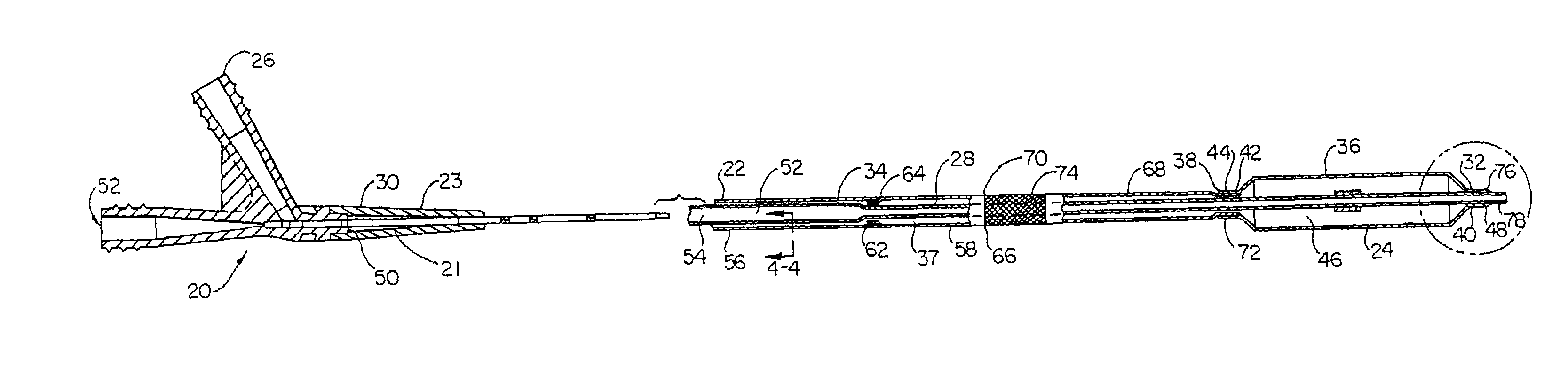
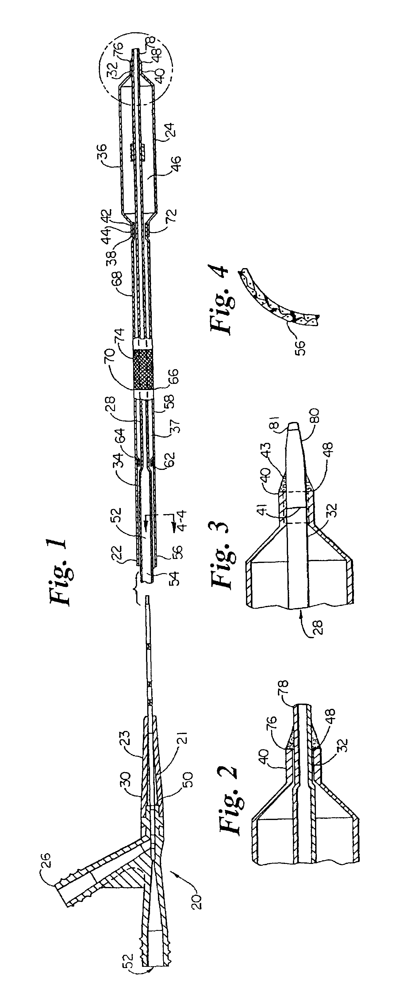
[0027]Referring now to the drawings, FIG. 1 is a cross-sectional view of an over-the-wire balloon catheter showing a preferred embodiment of the present invention. The balloon catheter 20 includes a shaft assembly 22 and a balloon assembly 24 connected proximate its distal end. A conventional OTW-type manifold assembly 26 is connected to the proximal end of th...


PUM

PropertyMeasurementUnit
thicknessaaaaaaaaaa
diameteraaaaaaaaaa
thicknessaaaaaaaaaa

Abstract

A spiral cut transition member is disclosed for controlling the transition in stiffness of a catheter from a stiffer more pushable proximal section to a more flexible and trackable distal section and increasing kink resistance. The transition member has a spiral cut provided therein to vary the flexibility of the transition member over its length. The pitch of the spiral cut can be varied to facilitate a gradual transition in flexibility along the catheter. The transition member may be used in conjunction with any type of catheter including single-operator-exchange type catheters, over-the wire type catheters, and/or fixed-wire type catheters.

Description

[0001]This application is a continuation of co-pending application Ser. No. 09 / 534,870 file date Mar. 24, 2000, which is a divisional of application Ser. No. 09 / 241,995, filed Feb. 2, 1999, now U.S. Pat. No. 6,048,338; which is a continuation-in-part of application Ser. No. 08 / 950,864, filed Oct. 15, 1997, now U.S. Pat. No. 5,891,110.TECHNICAL FIELD[0002]This invention relates to the field of intravascular medical devices, and more particularly, to intravascular catheters that use a relatively stiff proximal section and a more flexible distal section for improved pushability, trackability and crossability.BACKGROUND OF THE INVENTION[0003]Intravascular diseases are commonly treated by relatively non-invasive techniques such as percutaneous transluminal angioplasty (PTA) and percutaneous transluminal coronary angioplasty (PTCA). These therapeutic techniques are well known in the art and typically involve the use of a balloon catheter with a guide wire, possibly in combination with oth...

Claims


Application Information

Patent Timeline
Patent Type & Authority Patents(United States)
IPC IPC(8): B29C65/00A61M25/00B32B37/00A61F2/958A61M25/01A61M29/02
CPCA61M25/0054A61M25/104A61M25/1006A61M2025/0063A61M2025/0081A61M2025/0098
Inventor LARSON, CHRISTOPHER R.KORNKVEN, ANGELA J.
Owner BOSTON SCI SCIMED INC
Why Eureka
Try Eureka