Positioning and motion control by electrons, ions, and neutrals in electric fields

a technology of electrons and ions, applied in mechanical devices, machines/engines, instruments, etc., can solve the problems of inability to manufacture devices, toxic in the environment of the earth's surface environment, and no prior art that utilized field emission for force production, etc., to achieve less cost and greater ease of manufacture

Inactive Publication Date: 2006-10-03
RABINOWITZ MARIO +1
View PDF12 Cites 33 Cited by
  • Summary
  • Abstract
  • Description
  • Claims
  • Application Information

AI Technical Summary

Benefits of technology

[0064]There are many aspects and applications of this invention, which provides techniques applicable individually or in combination as an actuator, for motion control, and for positioning. The broad general concept of this invention relates to the actuation, motion production and control, and positioning resulting from the forece due to electron, ion, and neutrals in electric fields. The instant invention can perform dynamic motion control over a wide range of dimensions from the nano-range, through the micro-range, through the mini-range to the macro-range in a broad scope of applications from micro-electro-mechanical systems (MEMS) as in optical switching to macro-positioning. The signal bandwidth is unparalled, and can range from nanoseconds to static. Motorless linear motion, angular deflection, and continuous rotation are achieved without recourse to magnetic fields thus eliminating the need for coils. Furthermore, the instant invention permits less costly and greater ease of manufacture while providing well-defined motion and position control.
[0077]Another object of the instant invention is to produce a dynamic diffraction grating in which the grating spacing is varied and hence shift the wavelength selection.

Problems solved by technology

Except for applications in outer space such devices are for the most part not practical due to their size, weight and power requirements.
We found no prior art that utilized field emission for force production.
This engine produces ozone, which although it is compatible with and even needed in outer space, is toxic in the environment of the earth's surface.

Method used


Image

  • Positioning and motion control by electrons, ions, and neutrals in electric fields
  • Positioning and motion control by electrons, ions, and neutrals in electric fields
  • Positioning and motion control by electrons, ions, and neutrals in electric fields

Examples


Embodiment Construction

[0097]As is described here in detail, the objectives of the instant invention may be accomplished by any of a number of ways separately or in combination, as taught by our invention.

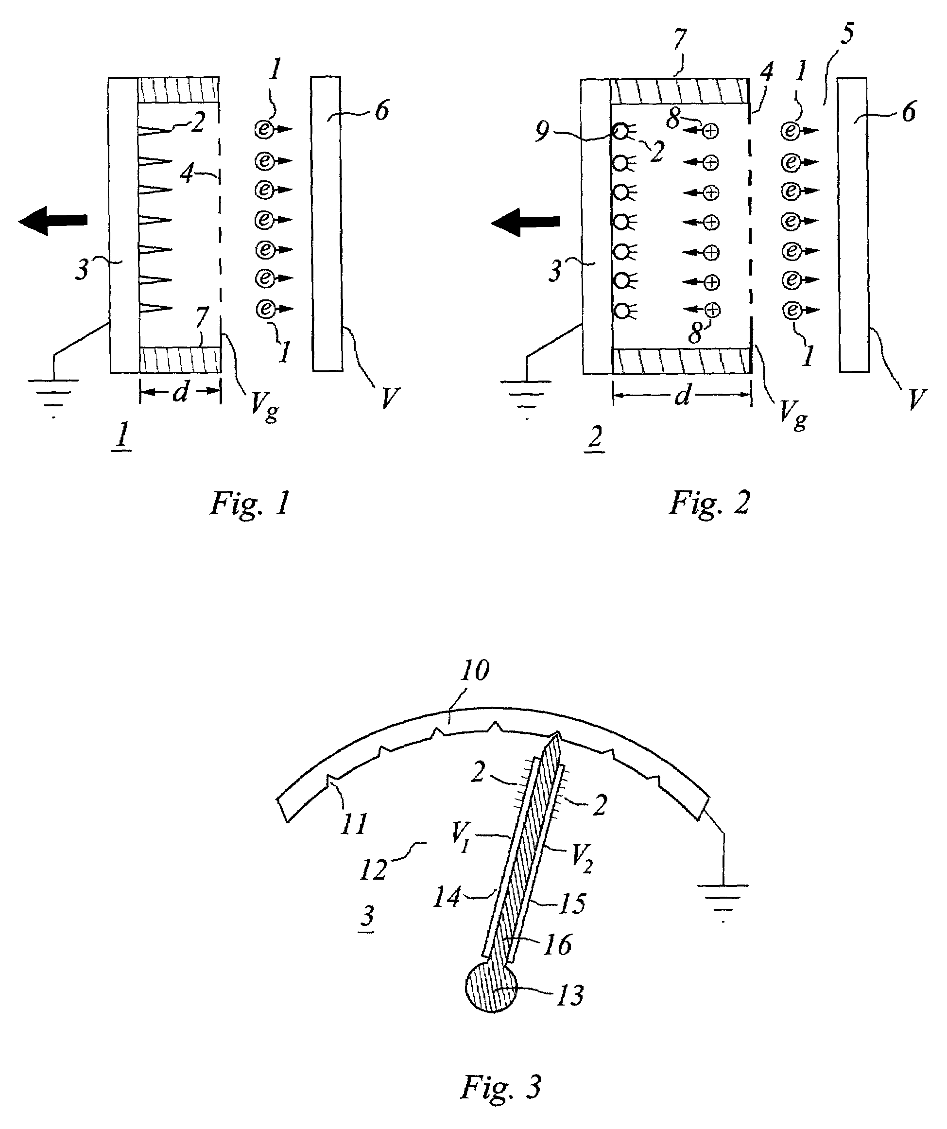
[0098]FIG. 1 shows a fundamental motive device 1, which in this case produces a force by the emission of electrons 1 from whiskers 2 on an electrode 3 that serves as cathode. Upon leaving the whiskers 2, the electrons 1 cross the gap d to pass through a grid 4 at voltage Vg to enter a region 5, and then are collected at the ultimate anode collector plate electrode 6 at voltage V≧Vg. When V=Vg, region 5 is field free. A dielectric 7 supports the grid 4 and electrically isolates the grid 4 from the electrode 3. The configuration of the grid 4 at fixed separation d from the electrode 3 serves to maintain an unchanging macroscopic electric field as motion is imparted to electrode 3. Otherwise the cathode-anode gap would change, requiring a modulation of the applied voltage to control the motive force. A repu...


PUM


Abstract

This invention deals with novel method and apparatus for positioning and motion control by rapid-response motorless linear motion, angular deflection, and continuous rotational motion utilizing the force due to electrons, ions, and / or neutrals. Thus forces and torques are produced without the use of internal moving parts. Control is achieved without recourse to magnetic fields, by means of high electric fields which may be attained at relatively low voltages. At low voltages, the instant invention exceeds the capability of conventional systems. It can perform dynamic motion control over a wide range of dimensions and signal bandwidth with independent amplitude and frequency modulation. Since there are no internal moving parts, the instant invention is the most adapted for fabrication at the micro and nanotechnology realms. Furthermore it provides less costly and greater ease of manufacture from the nano-to the macro-realm.

Description

BACKGROUND OF THE INVENTION[0001]1. Field of the Invention[0002]This invention relates generally to method and apparatus for positioning and motion control by the force due to electrons, ions, and / or neutrals. The instant invention can perform dynamic motion control over a wide range of dimensions and signal bandwidth. Motorless linear motion, angular deflection, and continuous rotation are achieved without recourse to magnetic fields. Preferably this invention lends itself readily to the field of nanotechnology, although it is also applicable to the macro-realm.[0003]2. Description of the Prior Art[0004]No prior art was found by us related to positioning and motion control by electrons, ions and neutrals in electric fields. The prior art has investigated various forms of rocket propulsion systems and ion engines for high altitude and space applications. The rocket and ion engines of the prior art are for a different purpose and use principles in a different way than the present inv...

Claims


Application Information

Patent Timeline
Patent Type & Authority Patents(United States)
IPC IPC(8): F03H3/00H05H1/00G01Q10/00F03H1/00G01Q60/00G01Q90/00
CPCF03H1/00
Inventor RABINOWITZ, MARIODAVIDSON, MARK
Owner RABINOWITZ MARIO
Why Eureka
Try Eureka