In practice, these switches are not ideal: they have power losses during their ON-state and they can't be switched from their OFF to their ON-state and back with an infinite speed, thus resulting into switching losses.
Although high speed switching allows the reduction of switching losses, it has some drawbacks when considering a complete installation comprising a motor drive, electrical cables and a motor.
Firstly, high speed
voltage switching stresses the motor and the electrical cables by driving capacitive currents into their insulations and bearings:
Capacitive currents may also contribute to the
electromagnetic interference (EMI) of the installation, thus generate electromagnetic perturbations for the neighboring devices.
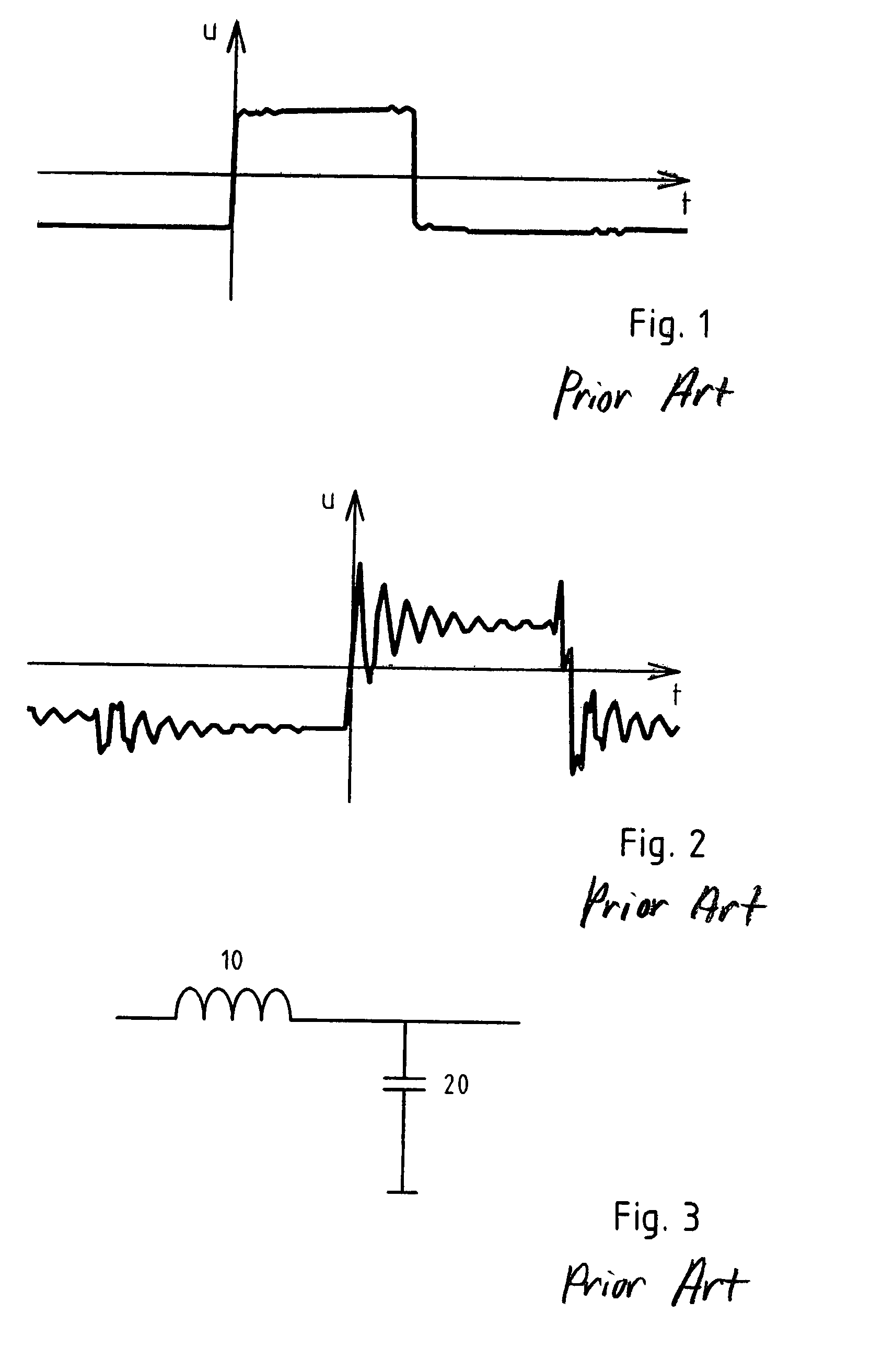
Secondly, and sometimes more importantly, high speed switching can give rise to significant
overvoltage oscillations at the motor end of the cable connecting the motor to the drive, particularly in the case of a long cable, which can lead to motor damages and / or to the breakdown of the cable's insulation.
Under such conditions, impedance discontinuities within the
transmission line will cause
voltage reflections leading to overvoltages as they add with the originally transmitted waveform.
This
overvoltage problem is even more severe with a 690V mains network systems where the
DC voltage may be 1100V, potentially resulting into overvoltage oscillations of 2200V while the maximum permissible motor voltage in many applications is typically only 1500V.
This solution however has the drawback that significant switching losses are present.
Moreover, setting the characteristics of the drive's elements is not always possible and / or desired.
Although such termination networks at the motor's end are well adapted for many applications, they are usually very lossy, thus releasing a lot of heat, and difficult to install near the motor.
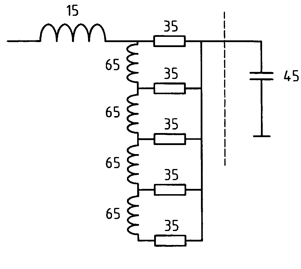
Although such simple filters made only of chokes or of chokes and capacitors are able, in most applications, to bring the du / dt-value into a suitable range in order to avoid overvoltages due to reflections, they have an important drawback:
the chokes themselves generate
voltage overshoot at their output, which is then propagated up to the motor along the cable.
This current flow will then cause the
voltage overshoot by charging the output capacitances.
However, for many applications a sinus-filter would be too expensive and bulky, and by filtering much more than a du / dt-filter it also negatively impacts the
system's dynamic response.
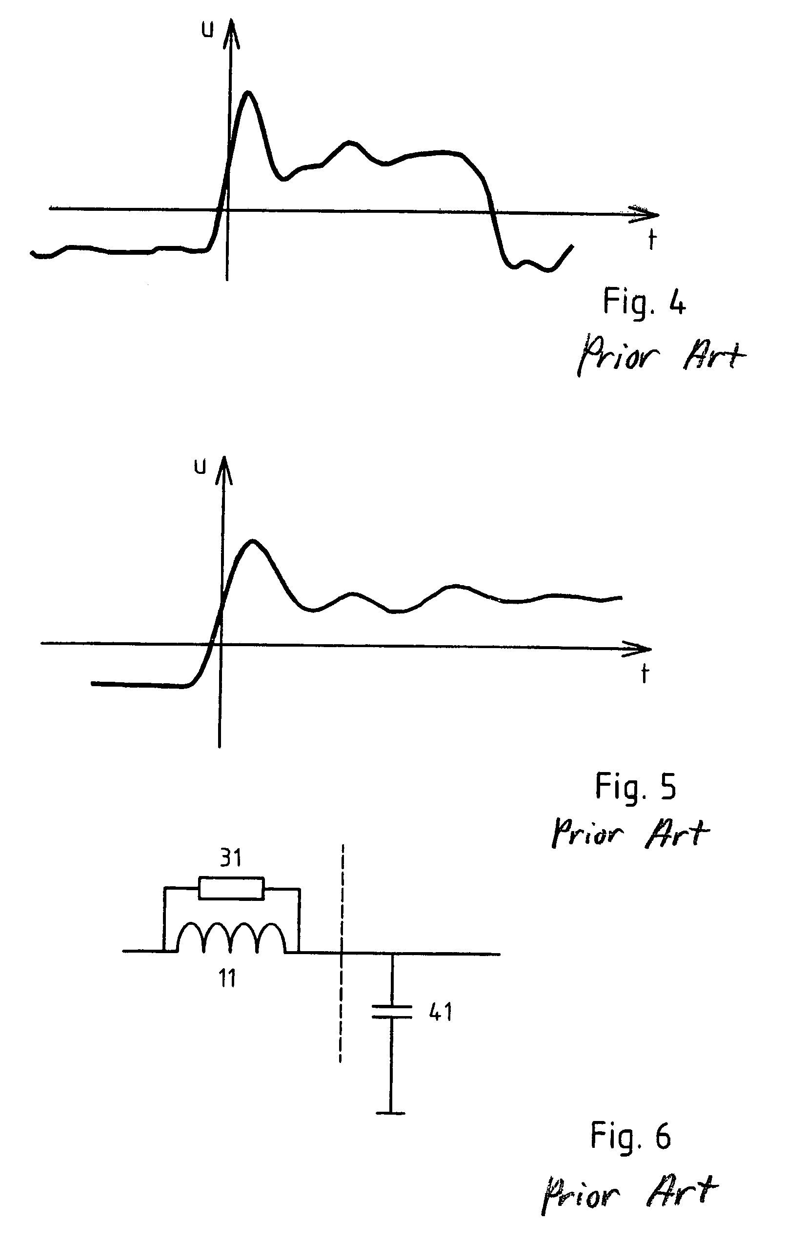
However, while the
discharge current is conducted by the
resistor 31, the energy is turned into losses which can typically reach several hundreds of watts when such a damped du / dt-filter is operated with a 200 meters long cable and with switching frequencies around 10 kHz.
A further drawback of such prior art du / dt-filters is that their behavior strongly depends on the value of the cable's
capacitance 41, which in turn depends on the cable's length.
However, this solution isn't effective in applications where the cable's ground-
capacitance and / or phase-to-phase
capacitance 42 is of a comparable magnitude as that of the filter's capacitance 22, which is the case in particular with long shielded (MCCMK) cables, because it doesn't attenuate the oscillations related to the
energy exchange between the filter's
choke 12 and the cable's capacitance 42, illustrated by the arrow in FIG. 10.
Apart of the low reliability and high cost of the diodes 53, the main drawback of this solution are the high magnitude and snappy currents related to voltage clamping, which is a violent voltage limitation.
In other words, although the voltage waveform may seem acceptable at the filter's output, the currents may have rapid changes and oscillations leading to high
electromagnetic interference.
One particular problem with this solution is that the energy stored in the filter's chokes 13 during the reduction of the voltage switching speed du / dt generates a so called free wheeling current flowing from the DC-link 63 through the
choke 13 and the diodes 53 and back to the DC-link 63.
This free wheeling current may for example corrupt the motor
estimation measurements done by the motor drive and as well as generating considerable energy losses within the diodes 53.
These impedance values don't provide
impedance matching, neither with the cable nor with the motor.

