Lithographic apparatus and device manufacturing method

a technology of lithographic apparatus and manufacturing method, which is applied in the direction of photomechanical apparatus, instruments, optics, etc., can solve the problems of reducing the quality of the pattern produced on the substrate, the quality of the image projected onto the substrate is not as good, and the reflection of the radiation from the substrate is minimized, so as to reduce the reflection of radiation

Inactive Publication Date: 2006-10-03
ASML NETHERLANDS BV
View PDF25 Cites 32 Cited by
  • Summary
  • Abstract
  • Description
  • Claims
  • Application Information

AI Technical Summary

Benefits of technology

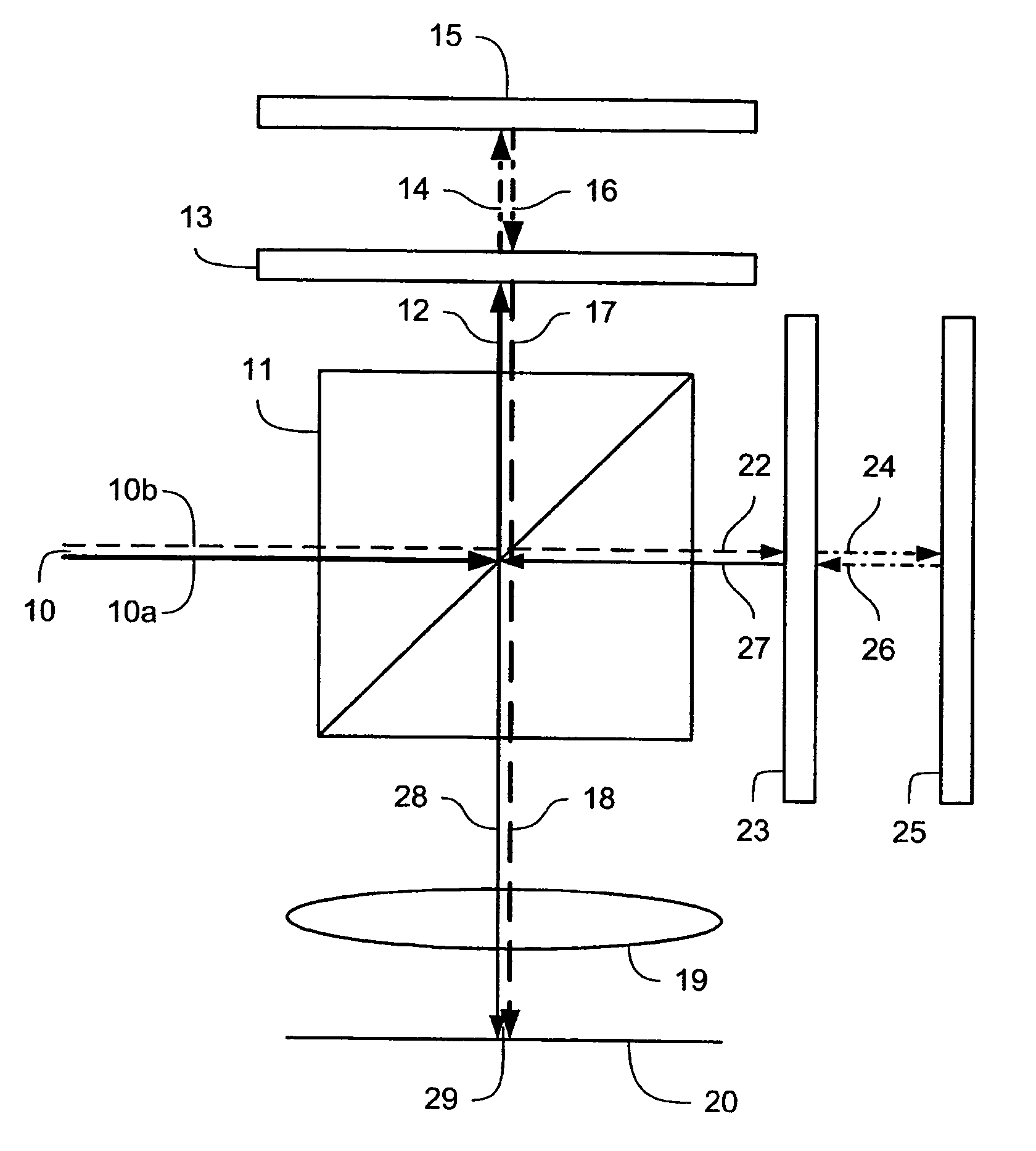
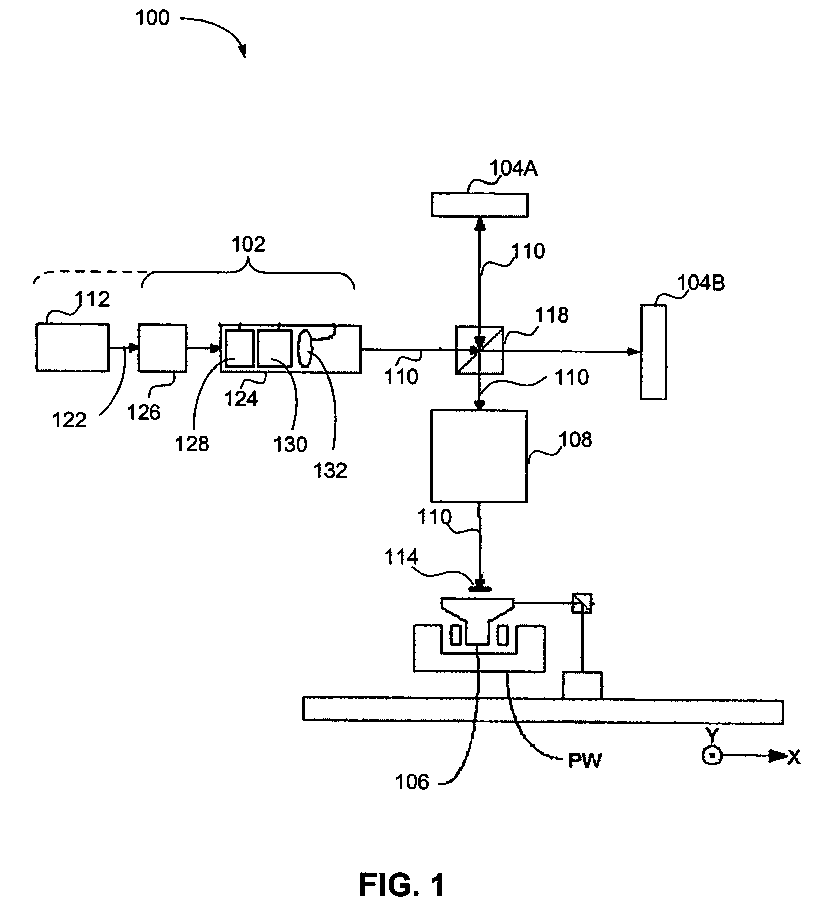
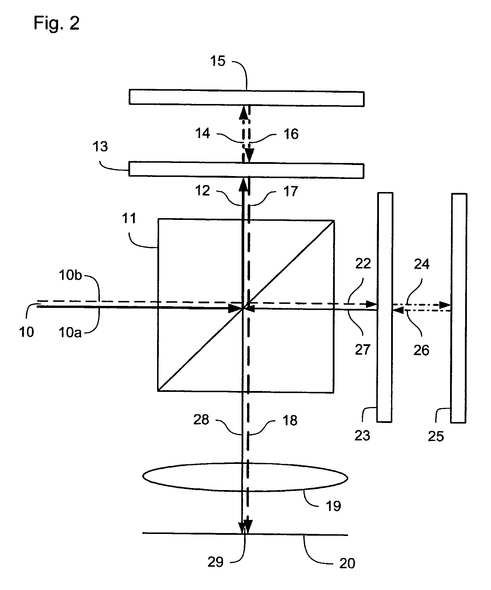
[0011]In this embodiment, a pattern to be projected onto the substrate can be divided into two sub-patterns set on the first and second arrays of individually controllable elements, which are them simultaneously imaged onto the substrate. In particular, elongate features in the pattern parallel to the given direction may be provided by the first array of individually controllable elements and elongate features perpendicular to the given direction may be provided by the second array of individually controllable elements. Therefore, illumination settings appropriate to the patterns set on each of the first and second arrays of individually controllable elements may be used. Furthermore, appropriate selection of the orientation of the linear polarization of the portions of the combined patterned beam may be used to reduce the reflection of the radiation from the substrate when the portion of the combined patterned beam is incident on the substrate at a high grazing angle.
[0012]In one example, the orientation of the linear polarization of the portion of the combined patterned beam derived from the first patterned beam is selected, such that the electric field of the portion of the beam of radiation lies in a plane that is perpendicular to a plane defined by the line along which the portion of the combined beam of radiation is projected onto the substrate (which is at an oblique angle to the substrate) and a line perpendicular to the substrate. The portion of the combined patterned beam derived from the second patterned beam may be arranged likewise. Consequently, the electric field of the radiation at the point at which it is incident on the substrate is parallel to the surface of the substrate. Therefore the reflection of the radiation from the substrate is minimized.
[0014]In one example, the radiation beam splitter and the radiation beam combiner are a single optical element or group of components. Consequently, where reflective arrays of individually controllable elements are used, they may be illuminated telecentrically. Furthermore, the number of components required is reduced, potentially reducing the complexity of the apparatus.
[0016]In this example, the portion of the projection beam of radiation that is appropriately linearly polarized to be initially reflected in the polarizing cube is subsequently rotated by passing through the quarter wavelength plate twice (before and after being incident on the array of individually controllable elements) and subsequently, when it next enters the polarizing cube, it is transmitted through the polarizing cube. Similarly, the portion of the projection beam of radiation appropriately linearly polarized to be initially transmitted through the polarizing cube is subsequently rotated by its double passage through the associated quarter wavelength plate, and is therefore reflected in the polarizing cube when it enters for the second time. Therefore, the beams of radiation patterned by the two arrays of individually controllable elements exit the polarizing cube for the second time together, namely are combined into a single patterned beam, and reflection of radiation in the direction of the radiation source is minimized.

Problems solved by technology

The disadvantage of such an arrangement is that two exposures are required for each complete pattern.
This arrangement avoids the loss of throughput for the apparatus, but the quality of the image projected onto the substrate is not as good as can be achieved with separate dipole illumination exposures.
The reflected radiation is stray radiation that can affect other parts of the apparatus or reduce the quality of the pattern produced on the substrate if reflected back to the substrate.
Furthermore, as the proportion of stray radiation increases, it is necessary to increase the intensity of the illumination radiation and / or increase the exposure time, thereby increasing the cost of the apparatus and / or reducing the throughput of the apparatus.

Method used


Image

  • Lithographic apparatus and device manufacturing method
  • Lithographic apparatus and device manufacturing method
  • Lithographic apparatus and device manufacturing method

Examples


Embodiment Construction

Overview and Terminology

[0031]Although specific reference may be made in this text to the use of lithographic apparatus in the manufacture of integrated circuits (ICs), it should be understood that the lithographic apparatus described herein may have other applications, such as the manufacture of integrated optical systems, guidance and detection patterns for magnetic domain memories, flat panel displays, thin-film magnetic heads, etc. The skilled artisan will appreciate that, in the context of such alternative applications, any use of the terms “wafer” or “die” herein may be considered as synonymous with the more general terms “substrate” or “target portion,” respectively. The substrate referred to herein may be processed, before or after exposure, in for example a track (e.g., a tool that typically applies a layer of resist to a substrate and develops the exposed resist) or a metrology or inspection tool. Where applicable, the disclosure herein may be applied to such and other sub...


PUM

PropertyMeasurementUnit
wavelengthaaaaaaaaaa

Abstract

Lithographic apparatus providing a patterned beam of radiation in which radiation that is linearly polarized in a first direction has a first pattern and radiation that is linearly polarized in an orthogonal direction has a second pattern.

Description

BACKGROUND OF THE INVENTION[0001]1. Field of the Invention[0002]The present invention relates to a lithographic apparatus and a device manufacturing method.[0003]2. Related Art[0004]A lithographic apparatus is a machine that applies a desired pattern onto a target portion of a substrate. The lithographic apparatus can be used, for example, in the manufacture of integrated circuits (ICs), flat panel displays, and other devices involving fine structures. In a conventional lithographic apparatus, a patterning means, which is alternatively referred to as a mask or a reticle, may be used to generate a circuit pattern corresponding to an individual layer of the IC (or other device), and this pattern can be imaged onto a target portion (e.g., comprising part of one or several dies) on a substrate (e.g., a silicon wafer or glass plate) that has a layer of radiation-sensitive material (e.g., resist). Instead of a mask, the patterning means may comprise an array of individually controllable e...

Claims


Application Information

Patent Timeline
Patent Type & Authority Patents(United States)
IPC IPC(8): G03B27/54G03B27/42G03B27/72G03F7/20
CPCG03F7/70225G03F7/70291G03F7/70425
Inventor TROOST, KARS ZEGERVAN DER MAST, KAREL DIEDERICK
Owner ASML NETHERLANDS BV
Why Eureka
Try Eureka