Wind power plant for generating energy

a wind power system and wind power technology, applied in the direction of wind power motors with parallel air flow, non-positive displacement fluid engines, liquid fuel engine components, etc., can solve the problems of hardly being used in a commercial way, the efficiency of known wind power systems is exceptionally low, and the size of known wind power systems is considerable (and especially length). , to achieve the effect of reducing the moment of inertia of the rotor, accelerating the start-up process, and high degr

Inactive Publication Date: 2006-10-10
GUDRUN WIESER
View PDF10 Cites 13 Cited by
  • Summary
  • Abstract
  • Description
  • Claims
  • Application Information

AI Technical Summary

Benefits of technology

[0008]A relevant share in increasing the efficiency of the wind power system in accordance with the invention is that virtually the entire projecting basic surface of the rotor will utilize the air flow, for which purpose it comprises the plurality of flow conduits for the air flow which are arranged in a rim-like distributed manner about the shaft, which individual flow conduits are each associated with a rotor. Each flow conduit thus comprises its own guide device with which it guides the air flow to the respective blades. As a result of the special embodiment of the individual flow conduits and the provision of the outside jacket which encloses the rotor, the dynamic pressure in front of the rotor is increased in addition, thus additionally accelerating the air flowing through the rotor. The blades can be provided for example in the flow conduits right up to the end of the flow conduit or even beyond the end of the flow conduit. If a construction is to be provided which is simple with respect to its design, then it is recommended to situate the blades downstream of the respective flow conduit.
[0011]In order to ensure the most constant speed of the rotor during gusty wind conditions for example, a disk flywheel can be associated which the rotor, which disk flywheel is held coaxially to the rotor and which is detachably connected with the rotor by means of a coupling. The disk flywheel is detached from the rotor during the start-up process for example in order to thus reduce the moment of inertia of the rotor and in order to accelerate the start-up process especially during low wind intensities. Once the rotor has reached its desired operating speed, the flywheel can then slowly be coupled with the rotor and thus finally be used as an energy storage means for compensating fluctuations in the rotational speed. An especially high moment of inertia and thus compensation capability for speed fluctuations and simple constructional conditions are obtained when the disk flywheel is arranged in the outer jacket of the rotor.
[0012]If a mobile use of the wind power unit in accordance with the invention is desired, it is erected on a carrying vehicle. Said carrying vehicle can be an excavator on whose boom the wind power unit is mounted. The tracking of the wind is governed in this case via the live ring of the chain vehicle. With out any additional means the chain vehicle can easily reach locations outside that are otherwise difficult to access.
[0014]The wind power system in accordance with the invention is arranged on a mast or the like with a horizontal rotational axis aligned against the wind or the rotor is held with a vertical axis in a tower which comprises a tower head which is adjustable coaxially to the rotor and comprises a pipe elbow which deflects the horizontal wind flow against the rotor, as result of which the pressure difference between upper and lower side of the tower, i.e. between inlet and outlet, can be used for winning power. If the wind speed is to be additionally increased by the rotor, then it is advantageous when the flow connection of the pipe elbow to the rotor narrows in the direction of flow.

Problems solved by technology

Known rotors come with the disadvantage however that their efficiency is exceptionally low especially at low wind speeds and at smaller diameters.
Such known wind power systems have a considerable size (and especially length), which is why they can hardly be used extensively in a commercial way, especially in the private field.

Method used


Image

  • Wind power plant for generating energy
  • Wind power plant for generating energy
  • Wind power plant for generating energy

Examples


Embodiment Construction

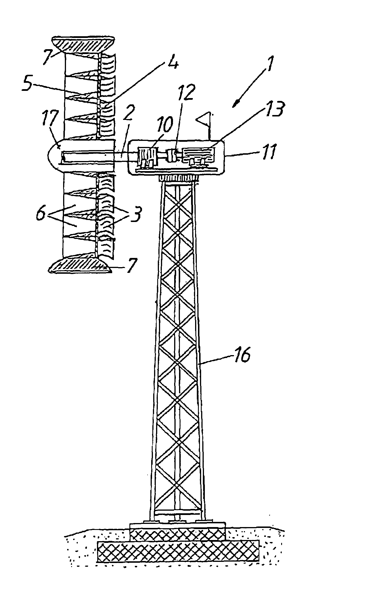
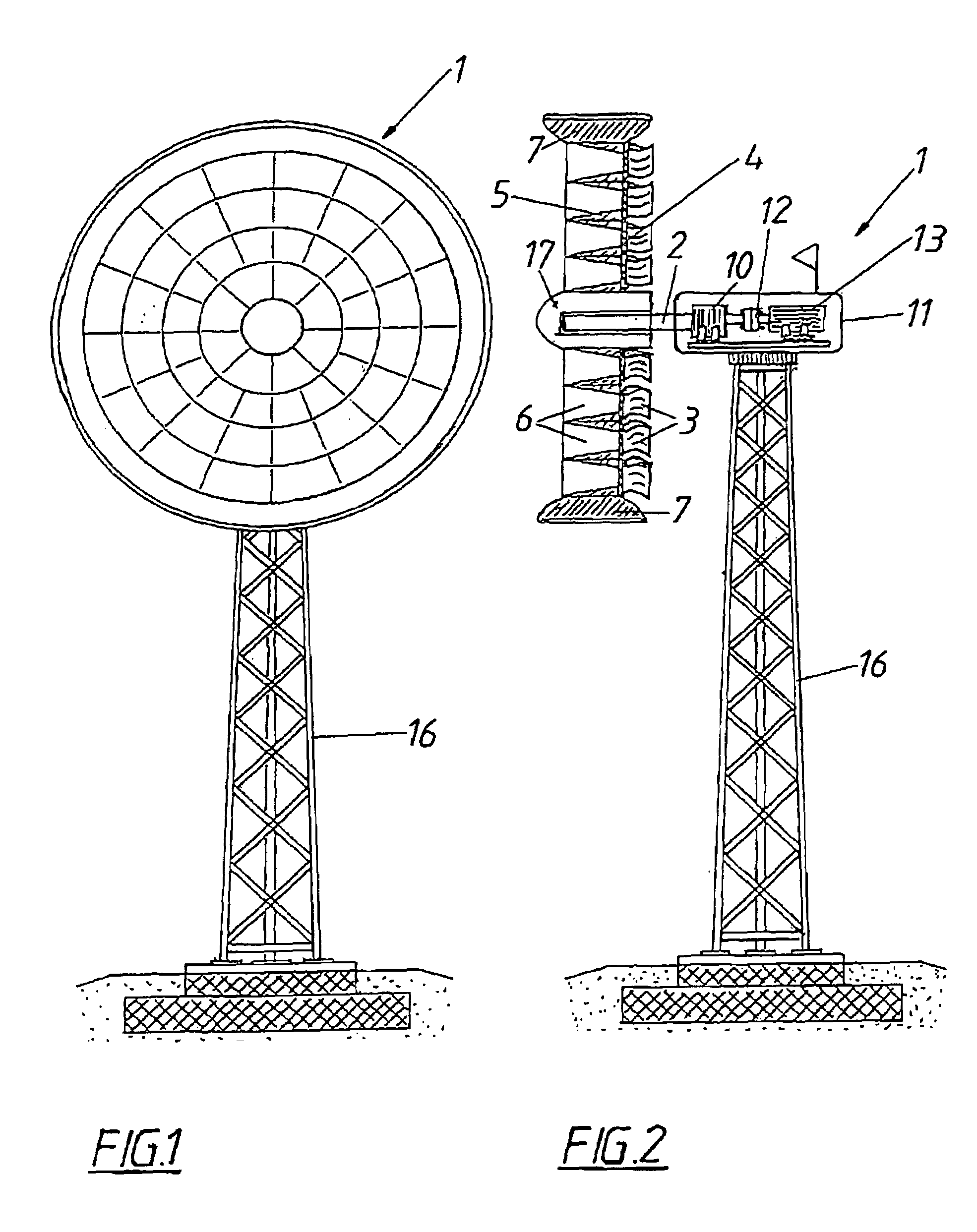
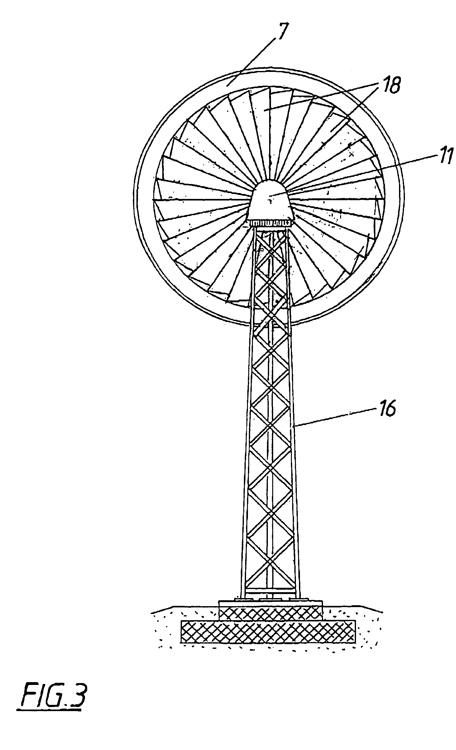
[0027]A wind power system 1 for generating power substantially consists of a rotor 4 which is flowed through axially, is fastened to a shaft 2 and is provided with rotor blades 3, and of a guide device 5 which accelerates the air flow through the rotor 4. The guide device 5 is composed of several flow conduits 6 which taper in the direction of flow. Said flow conduits 6 are arranged in a rim-like manner with their guide devices 5 on the rotor 4 distributed around the shaft 2 in order to utilize the air flow over the entire cross section of the rotor 4 against which the air flows. The blades 3 are each situated downstream of a flow conduit 6 and the rotor 4 comprises an outside jacket 7 which encloses the same. Said outside jacket has the shape of a concentric nozzle in order to increase the dynamic pressure in front of the rotor 4. Similarly, the rim-like guide devices 5 increase the dynamic pressure. Downstream of the rotor 4 there is an auxiliary rotor 18 which is not shown in clo...


PUM


Abstract

A wind power system (1) for generating power is proposed, comprising a rotor which is axially flowed through, is rotatably held on a shaft (2) and is provided with blades (3), as well as a guide device (5) which accelerates the air flow through the rotor (4). In order to provide advantageous conditions for generating power it is proposed that the guide device (5) consists of several flow conduits (6) tapering in the direction of flow, which conduits are arranged on the rotor (4) in a distributed way in the manner of a rim around the shaft (2), that the blades (3) are associated with one flow conduit (6) each and that the rotor (4) comprises an outside jacket (7) enclosing the same.

Description

CROSS REFERENCE TO RELATED APPLICATIONS[0001]Applicants claim priority under 35 U.S.C. §119 of Austrian Applications No. A 1238 / 01 filed on Aug. 8, 2001 and A 1646 / 01 filed on Oct. 17, 2001. Applicants also claim priority under 35 U.S.C. §365 of PCT / AT02 / 00238 filed on Aug. 7, 2002. The international application under PCT article 21(2) was not published in English.[0002]1. Field of the Invention[0003]The invention relates to a wind power system for generating power with a rotor which is axially flowed through, is rotatably held on a shaft, is provided with blades and is provided with a guide device which accelerates the air flow through the rotor.[0004]2. Description of the Prior Art[0005]Conventional wind power systems usually have propeller-like rotors which are aligned in or against the wind direction for producing power. Known rotors come with the disadvantage however that their efficiency is exceptionally low especially at low wind speeds and at smaller diameters. In order to i...

Claims


Application Information

Patent Timeline
Patent Type & Authority Patents(United States)
IPC IPC(8): B63H1/16F03D1/04
CPCF03D1/04F05B2240/13F05B2240/131Y02E10/721Y02E60/16Y02E10/728F05B2240/33F03D9/12F03D9/32Y02E10/72Y02E70/30
Inventor WIESER, GERHARD
Owner GUDRUN WIESER
Why Eureka
Try Eureka