
Parallel flow reactor having improved thermal control

Inactive Publication Date: 2006-10-10
FREESLATE
View PDF89 Cites 58 Cited by
  • Summary
  • Abstract
  • Description
  • Claims
  • Application Information

AI Technical Summary

Benefits of technology

[0007]It is therefore an object of the present invention to provide apparatus and methods for more efficient identification and / or optimization of materials and / or temperature conditions in chemical processing systems (e.g., chemical reaction systems), where temperature can be independently significant with respect to performance in the application of interest.
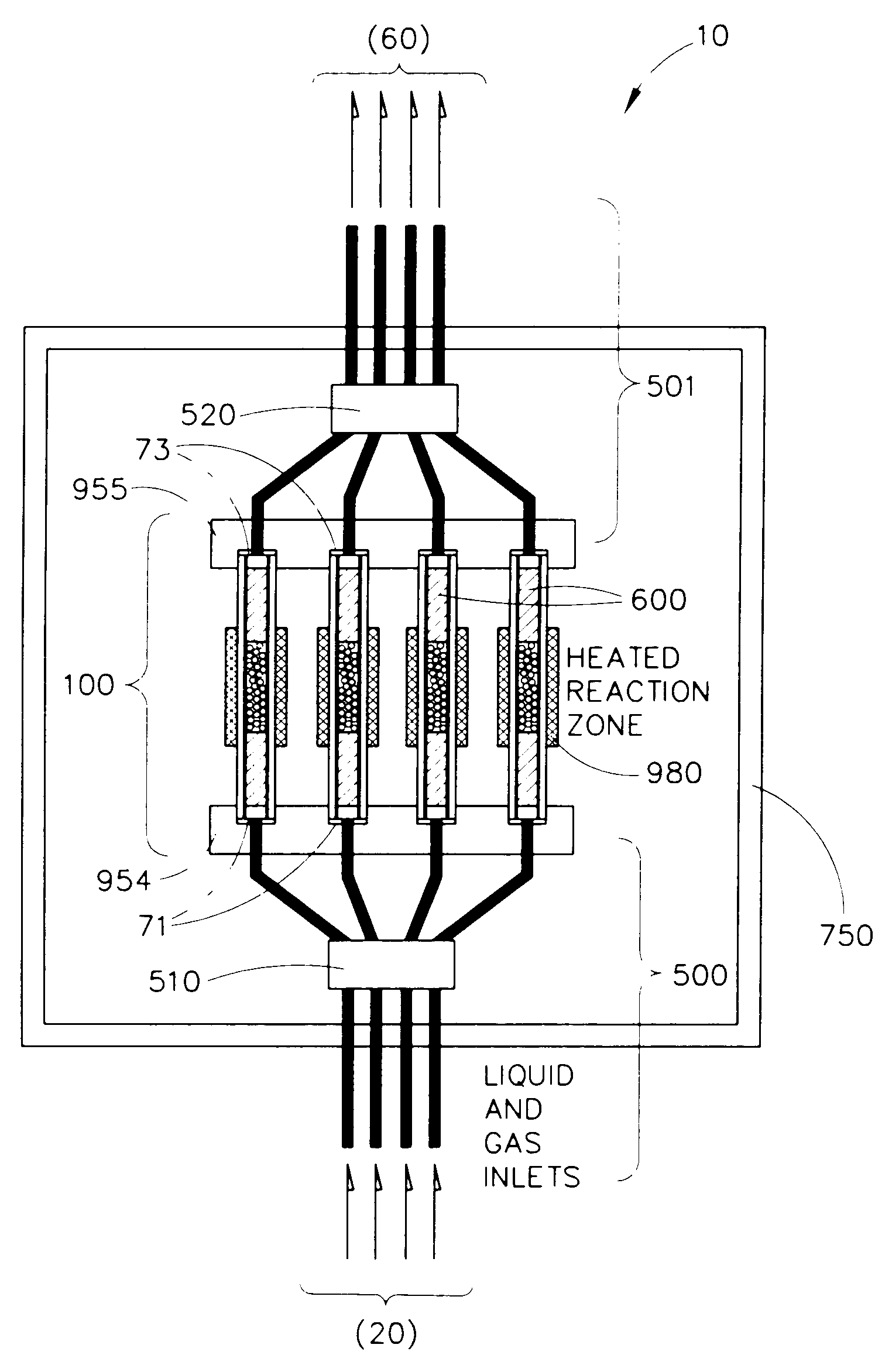
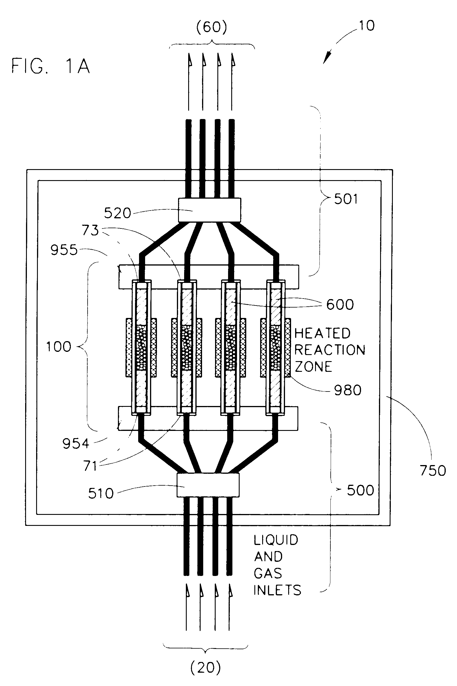
[0009]The invention is directed, in one embodiment, to parallel reaction systems having the capability to simultaneously and independently vary temperature between separate channels. The parallel flow reaction systems can generally include a reactor module that comprises four or more parallel flow reactors having separate and independent temperature control for each of the four or more reactors. Preferably, the temperature control system is adapted to provide individually variable temperature differences of at least about 5° C., preferably at least about 10° C. as compared between four or more spatially adjacent reactors. Advantageously, in some embodiments, the thermal control system of the reaction system is capable of providing even higher temperature differences between spatially adjacent reactors—such as at least about 20° C., at least about 50° C., at least about 100° C., at least about 150° C. or at least about 200° C.

Problems solved by technology

More specifically for example, in the context of heterogeneous catalysis research, only limited attention has been focused on the development of apparatus and methods for high-throughput, parallel optimization of important parameters such as catalyst (or catalyst precursor) processing conditions and reaction conditions.
These and other reactor designs known in the art do not, however, specifically address approaches or contemplate apparatus for investigating and / or optimizing reaction temperature—simultaneously and independently—in relatively closely-packed, highly parallel reactors.
As reactor dimensions become reduced, and as the spatial density of reactors increases, significant thermal cross-talk between reaction vessels can be a substantial obstacle for achieving simultaneous and independent temperature control in such reaction systems.

Method used


Image

  • Parallel flow reactor having improved thermal control
  • Parallel flow reactor having improved thermal control
  • Parallel flow reactor having improved thermal control

Examples


Embodiment Construction

[0020]The present invention is related to the following patents and / or patent applications, each of which is hereby incorporated by reference for all purposes, including for the purpose of combination of various features disclosed in the various related applications to various features disclosed herein, to the highest extent practical, based on the knowledge in the art, and coupled with the guidance of this application and the related applications: (1) co-owned U.S. patent application Ser. No. 60 / 187,566 entitled “Apparatus and Methods for Multi-Variable Optimization of Reaction Systems and Other Chemical Processing Microsystems”, filed Mar. 7, 2000 by Bergh et al, (2) co-owned U.S. patent application Ser. No. 60 / 229,984 entitled “Apparatus and Methods for Optimization of Process Variables in Reaction Systems and Other Chemical Processing Systems”, filed Sep. 2, 2001 by Bergh et al; (3) co-owned U.S. Pat. No. 6,149,882 to Guan et al. entitled “Parallel Fixed-Bed Reactor and Fluid Co...


PUM


Abstract

Parallel flow chemical processing systems, such as parallel flow chemical reaction systems are disclosed. These systems are adapted to simultaneously and independently vary temperature between separate flow channels, preferably by employing separate, individual heating elements in thermal communication with each of four or more parallel flow reactors. The flow reactors are preferably isolated from each other using a thermal isolation system comprising fluid-based heat exchange. In preferred embodiments, the axial heat flux can be fixedly or controllably varied.

Description

[0001]This application claims priority to co-owned, U.S. Ser. No. 60 / 274,065 entitled “Parallel Flow Reactor Having Improved Thermal Control” filed Mar. 7, 2001 by Bergh et al.BACKGROUND OF INVENTION[0002]The present invention generally relates to materials science research, and specifically, to combinatorial (i.e., high throughput) materials science research directed toward the identification and / or optimization of new materials. The invention particularly relates, in preferred embodiments, to apparatus and methods for optimizing chemical reaction systems, such as chemical reaction systems involving heterogeneous catalysts.[0003]In recent years, significant efforts have been extended toward developing parallel systems, such as parallel reactors, for the purpose of screening different materials, such as heterogeneous catalysts, for particular properties of interest, such as catalysis. U.S. Pat. No. 5,985,356 to Schultz et al. discloses synthesis and screening arrays of materials in ...

Claims


Application Information

Patent Timeline
IPC IPC(8): G01N31/00B01J19/00B01L3/00B01L7/00C40B30/08C40B40/18C40B60/14
CPCB01J19/0046B01L3/5027B01L7/00B01L7/54B01J19/0093Y10T436/2575B01J2219/00286B01J2219/00308B01J2219/00495B01J2219/00587B01J2219/00689B01J2219/00698B01J2219/00707B01J2219/0072B01J2219/00745B01J2219/00747B01J2219/00788B01J2219/0081B01J2219/00835B01J2219/0086B01J2219/00869B01J2219/00873B01J2219/0095B01J2219/00961B01L2300/0861B01L2300/18B01L2300/1883C40B30/08C40B40/18C40B60/14
Inventor BERGH, H. SAMGUAN, SHENHENGENGSTROM, JAMES R.HARDT, STEFFENLOHF, ASTRIDMICHEL, FRANK
Owner FREESLATE
Learn More