
Drive control device for direct current motor, rotation drive system for direct current motor and semiconductor integrated circuit for driving coil

Inactive Publication Date: 2006-10-10
RENESAS TECH CORP
View PDF9 Cites 27 Cited by
  • Summary
  • Abstract
  • Description
  • Claims
  • Application Information

AI Technical Summary

Benefits of technology

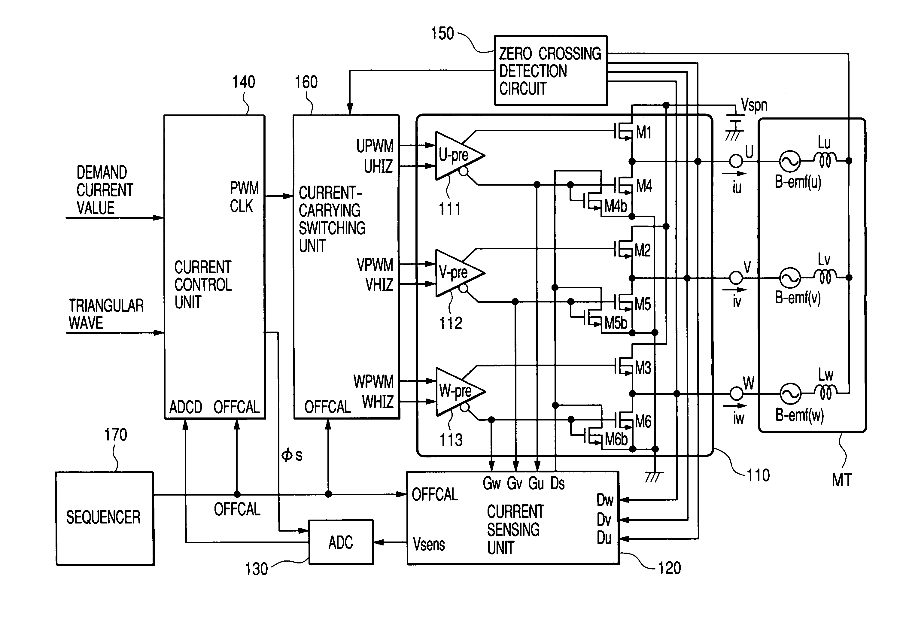
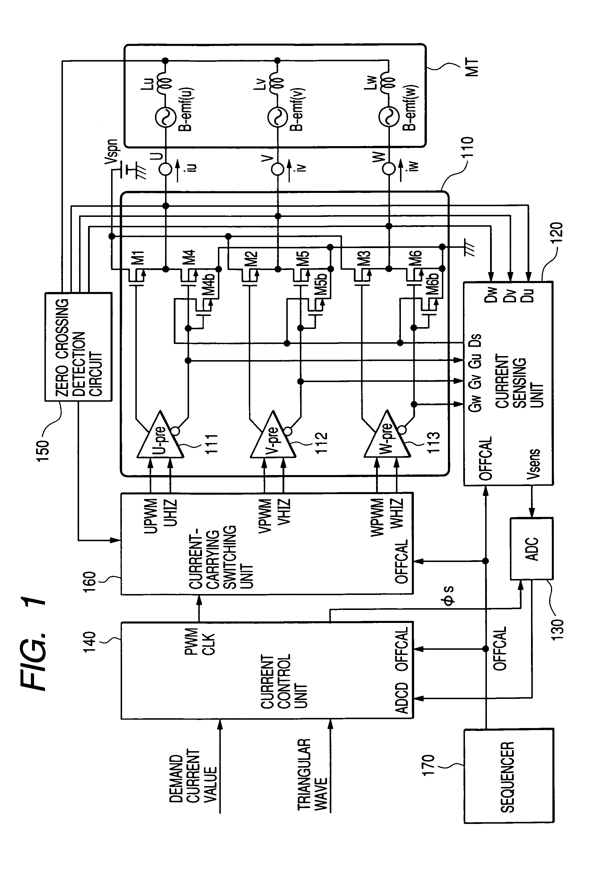
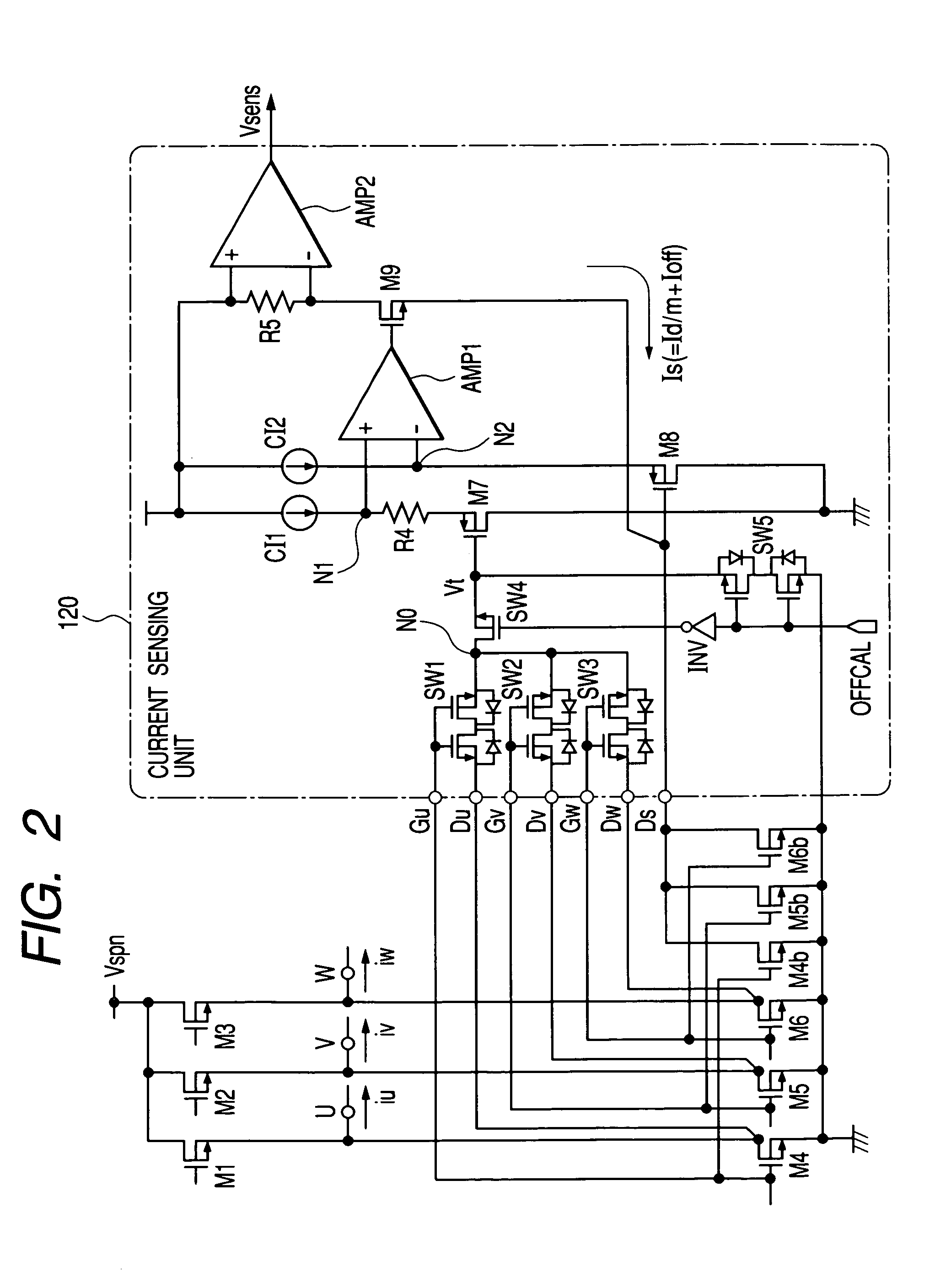
[0016]According to the above construction, even when the output MOS transistors are configured to operate in the non-saturation region, the drain terminals of the current sensing MOS transistors are supplied with the voltages identical to the drain voltages of the output MOS transistors. Therefore, it is possible to make flow the currents accurately proportional to the currents of the output MOS transistors into the current sensing MOS transistors. By detecting the currents, the currents flowing into the MOS transistors can be detected without using the conventional shunt resistors, which makes it possible to control the drive currents of the coils with a high accuracy.

Problems solved by technology

However, in the current sensing system using the shunt resistors, since the switching transistors and the shunt resistors are connected in series between the terminal for a power supply voltage and the grounding point, the voltages applied to the coils are lowered to decrease the power efficiency.
And, since the externally connected high-accuracy and expensive resistive elements are needed for the high-accuracy control, the cost is inevitably increased.
However, the formerly filed inventions did not adopt the PWM control system as the drive control of the motor.
Therefore, to merely apply the current sensing system of these formerly filed inventions as it is to the motor drive system of the PWM control system is hard to implement a high-accuracy rotation drive control.

Method used


Image

  • Drive control device for direct current motor, rotation drive system for direct current motor and semiconductor integrated circuit for driving coil
  • Drive control device for direct current motor, rotation drive system for direct current motor and semiconductor integrated circuit for driving coil
  • Drive control device for direct current motor, rotation drive system for direct current motor and semiconductor integrated circuit for driving coil

Examples


second embodiment

[0084]FIG. 10 illustrates the current sensing unit 120 relating to the motor drive control device according to the invention. The current sensing unit 120 of this embodiment is suitable for the system that allows the PWM pulse drive to the coils for two phases (not one phase) of the three phase coils, in order to reduce the current variations during current switching and decrease the noises in the drive control for the three-phase dc motor. The difference from the current sensing unit 120 of the embodiment in FIG. 2 is that an offsetting second resistor R4′ and a switch SW9 in series form are connected in parallel to the offsetting resistor R4. Here, the resistor R4′ is designed to have the resistance equal to that of the R4.

first embodiment

[0085]The current sensing unit 120 of this embodiment permits the current detection in the two-phase PWM drive as well as the current detection in the one-phase PWM drive. In the one-phase PWM drive, the switch SW9 is turned off, and the current flowing into the coil is detected with the same operation as in the In the two-phase PWM drive, the switch SW9 is turned on. In the two-phase PWM drive, there is a period during which are turned on simultaneously the transistors for the two phases of the low potential side output MOS transistors M4 to M6 in the output driver circuit 110. In this period, the drive current is made to flow dividedly into any two transistors for the two phases of the low potential side output MOS transistors M4 to M6.

[0086]And, in response to the state that the transistors for the two phases of the low potential side output MOS transistors are turned on, any two transistors of the current sensing MOS transistors M4bto M6b are turned on, and the resistance viewe...


PUM


Abstract

A dc motor drive system with a PWM control system permits a high-accuracy rotation drive control while detecting the currents flowing into the coils without using shunt resistors. The system drives output MOS transistors by the PWM control to make the currents flow into the coils, and drives to rotate the dc motor. The system includes current sensing MOS transistors having a predetermined size ratio 1 / m (M>1) to the output MOS transistors that make the currents flow into the coils. The current sensing MOS transistors are capable of making flow reduced currents proportional to the currents of the output MOS transistors.

Description

CROSS-REFERENCE TO RELATED APPLICATION[0001]The present application claims priority from Japanese patent application JP 2003-087010 filed on Mar. 27, 2003, the content of which is hereby incorporated by reference into this application.BACKGROUND OF THE INVENTION[0002]The present invention relates to a drive control technique for a brushless motor (also called permanent-magnet synchronous motor), and a technique effective for application to the PWM (Pulse Width Modulation) drive control of a three-phase dc motor, for example, a technique effective for use in a drive control device for a spindle motor that drives to rotate a disk-type storage medium such as a hard disk.[0003]A hard disk drive uses a brushless three-phase dc motor being generally called the spindle motor in order for rotating a magnetic disk. While rotating the magnetic disk with the spindle motor at a high speed, and bringing a magnetic head for reading / writing close to the surface of the rotating magnetic disk to tra...

Claims


Application Information

Patent Timeline
IPC IPC(8): H02K21/00H02K23/00H02K31/00H02P1/18H02P3/08H02P6/16G11B19/28H02M7/5387H02P6/06H02P6/08H02P6/18H02P6/182H02P6/28
CPCG11B19/28H02M7/53875H02P6/002H02M2001/0009H02P6/28H02M1/0009
Inventor KUROSAWA, MINORUMATSUSHITA, TSUKASAKAWAUCHI, KUNIHIRO
Owner RENESAS TECH CORP
Learn More