Surface light source device, diffusion plate and liquid crystal display device

a liquid crystal display device and surface light source technology, applied in lighting and heating devices, mechanical devices, instruments, etc., can solve the problems of difficult to narrow the emission range of light emitted from the liquid crystal display device, limit the reduction of power consumption, and prior art lack of devices for narrowing the beam spread angle, so as to reduce the unevenness of radial luminance

Inactive Publication Date: 2006-10-17
TOHOKU DENSHI CO LTD
View PDF1 Cites 64 Cited by
  • Summary
  • Abstract
  • Description
  • Claims
  • Application Information

AI Technical Summary

Benefits of technology

[0021]The present invention has been implemented in view of the foregoing problems of the prior arts, and has an object to reduce radial luminance unevenness occurring in a surface light source device.

Problems solved by technology

Therefore, there is a limit to the reduction of the number of LEDs 7, and thus there is also a limit to the reduction in power consumption.
However, when a diffusion plate is used as in the case of the surface light source device as the first prior art, light is emitted in all the directions, and thus it is difficult to narrow the emission range of light emitted from the liquid crystal display device.
Therefore, this prior art has no device for narrowing the angle of beam spread (hereinafter referred to as “directivity angle”) of light.

Method used


Image

  • Surface light source device, diffusion plate and liquid crystal display device
  • Surface light source device, diffusion plate and liquid crystal display device
  • Surface light source device, diffusion plate and liquid crystal display device

Examples


first embodiment

(First Embodiment)

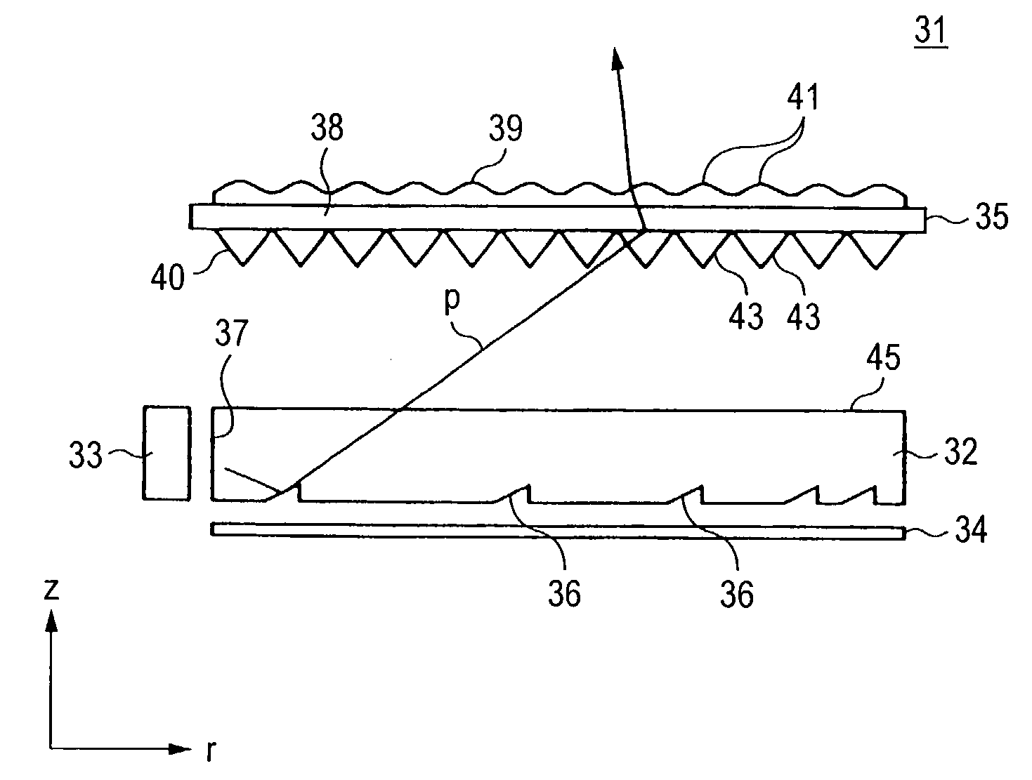
[0087]FIG. 7 is an exploded perspective view showing the structure of a surface light source device 31 according to a first embodiment of the present invention, and FIG. 8 is a cross-sectional view schematically showing the surface light source device 31 of FIG. 7.

[0088]The surface light source device 31 shown in FIG. 7 mainly comprises a light guide plate 32, a light emitting portion 33, a reflection plate 34 and a diffusion prism sheet 35. The light guide plate 32 is formed of transparent resin such as polycarbonate resin, methacrylic resin or the like to have a rectangular flat shape, and is equipped with light diffusion patterns 36 on the back surface thereof. Furthermore, a light incident face 37 is formed at a place of a corner portion of the light guide plate by cutting out the corner portion obliquely in plan view.

[0089]The light emitting portion 33 (not shown) is formed by sealing one or plural LEDs in transparent mold resin and covering the surfaces other...

second embodiment

(Second Embodiment)

[0133]FIG. 32 is a perspective view showing the structure of a surface light source device according to another embodiment of the present invention. FIG. 33A is a plan view showing an uneven diffusion plate 53 of a diffusion prism sheet 52 used in the surface light source device 51, FIG. 33B is an enlarged view of a Y portion of FIG. 33A, and FIG. 33C is a cross-sectional view taken along Z—Z line of FIG. 33B. In the surface light source device 51 of this embodiment, the structures of the light guide plate 32, the light emitting portion and the reflection plate 34 are the same as the first embodiment.

[0134]The diffusion prism sheet 52 has the uneven diffusion plate 53 formed on the obverse surface thereof and the prism sheet 40 formed on the back surface thereof. The prism sheet 40 is the same as the first embodiment (see FIG. 11). The uneven diffusion plate 53 is designed to diffuse light transmitted through the prism sheet 40 only in the ω direction. That is, as...

third embodiment

(Third Embodiment)

[0139]FIG. 36 shows the sectional shape on the zr plane of the prism sheet 56 of the uneven diffusion plate used in another embodiment of the present invention. In this prism sheet 56, a slope surface (reflection face) 58 remoter from the light emitting portion 33 in the slope surfaces constituting the prism in section is bent so as to project from some midpoint thereof to narrow the directivity in the φ direction, thereby enhancing the brightness in the vertical direction and also reducing the radial luminance unevenness.

[0140]FIG. 37 shows the directivity in the φ direction of light transmitted through the prism sheet 56. The abscissa axis represents the angle φ measured from the z axis and the ordinate axis represents the light intensity. This was a simulation result achieved on the basis of a prism sheet 56 in which the inclination angle δ of the slope surface (incident face) 57 nearer to the light emitting portion 33 was equal to 74°, the inclination angle ε o...


PUM

PropertyMeasurementUnit
oblique angleaaaaaaaaaa
sizeaaaaaaaaaa
sizeaaaaaaaaaa

Abstract

A point-light-source type light emitting portion faces a light incident face located at a corner portion of a light guide plate. A light diffusion pattern for emitting the light in the light guide plate from a light emission face is on the lower surface of the light guide plate. A diffusion prism sheet is on the light emission face. A prism sheet including prisms each having a concentric shape with the light emitting portion at the center is on the lower surface of the diffusion prism sheet, and an uneven diffusion plate is on the upper surface of the diffusion prism sheet. Light emitted from the light emission face of the light guide plate along the light emission face is deflected in the direction perpendicular to the light guide plate by the prism sheet, and the angle of beam spread of the light is spread by the uneven diffusion plate.

Description

BACKGROUND OF THE INVENTION[0001]1. Field of the Invention[0002]The present invention relates to a surface light source device, a diffusion plate and a liquid crystal display device, and particularly to a surface light source device used as a back light for a liquid crystal display panel or the like, a diffusion plate for the surface light source device and a liquid crystal display device using the surface light source device.[0003]2. Description of the Related Art[0004]A surface light source device is used as a back light or the like for a transmission type liquid crystal display panel. The liquid crystal panel generates an image by transmitting or intercepting light every pixel. The liquid crystal display panel has no function of spontaneously emitting light, and thus it needs a surface light source device for back light.[0005]FIG. 1 is an exploded perspective view showing the structure of a conventional surface light source device 1, and FIG. 2 is a cross-sectional view of FIG. 1...

Claims


Application Information

Patent Timeline
Patent Type & Authority Patents(United States)
IPC IPC(8): G02B6/00F21V3/00F21V5/00F21V8/00F21Y101/02G02F1/13357H01L33/22H01L33/54H01L33/56
CPCG02B6/0036G02B6/0038G02B6/0053G02B6/0061G02B6/0051G02F1/133615G02F2001/133607G02F1/133607G02F1/1335
Inventor SHINOHARA, MASAYUKIMINOBE, TETSUYAMAKUTA, ISAOUENO, YOSHIHIROYABE, MAMORU
Owner TOHOKU DENSHI CO LTD
Why Eureka
Try Eureka