Artificial intervertebral disc having a spider spring force restoring element

a technology of artificial intervertebral discs and springs, which is applied in the field of spinal implant assemblies, can solve the problems of collateral injury to the patient's spine, limiting the overall flexibility of the spinal column, and limiting the normal motion of the patien

Inactive Publication Date: 2006-10-17
HOWMEDICA OSTEONICS CORP
View PDF25 Cites 47 Cited by
  • Summary
  • Abstract
  • Description
  • Claims
  • Application Information

AI Technical Summary

Benefits of technology

[0029]Each assembly with a spider spring enjoys spring-like performance with respect to axial compressive loads, as well as long cycle life to mimic the axial biomechanical performance of the normal human intervertebral disc. The separate spring arms of the spider spring allow the spider spring to expand radially as the spring arms further separate under the compressive load, only to spring back into its undeflected shape when it is unloaded. As the spider spring compresses and decompresses, the walls of the circular recess of the second plate embodiment maintain the wide end of the spider spring within a prescribed boundary on the inwardly facing surface of the plate. The assemblies withstand tension loads on the outwardly facing surfaces, because (in embodiments having a spider spring) the shield retains the wide end in the circular recess and because (in embodiments having the ball-shaped protuberance) the rivet in the axial bore prevents the ball-shaped protuberance from deflecting, thus preventing it from exiting the curvate socket ...

Problems solved by technology

It is, however, important to note that the fusion of the adjacent bones is an incomplete solution to the underlying pathology as it does not cure the ailment, but rather simply masks the pathology under a stabilizing bridge of bone.
This bone fusion limits the overall flexibility of ...

Method used


Image

  • Artificial intervertebral disc having a spider spring force restoring element
  • Artificial intervertebral disc having a spider spring force restoring element
  • Artificial intervertebral disc having a spider spring force restoring element

Examples


Embodiment Construction

[0094]While the invention will be described more fully hereinafter with reference to the accompanying drawings, in which particular embodiments and methods of implantation are shown, it is to be understood at the outset that persons skilled in the art may modify the invention herein described while achieving the functions and results of the invention. Accordingly, the descriptions that follow are to be understood as illustrative and exemplary of specific structures, aspects and features within the broad scope of the invention and not as limiting of such broad scope. Like numbers refer to similar features of like elements throughout.

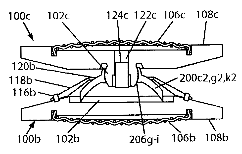
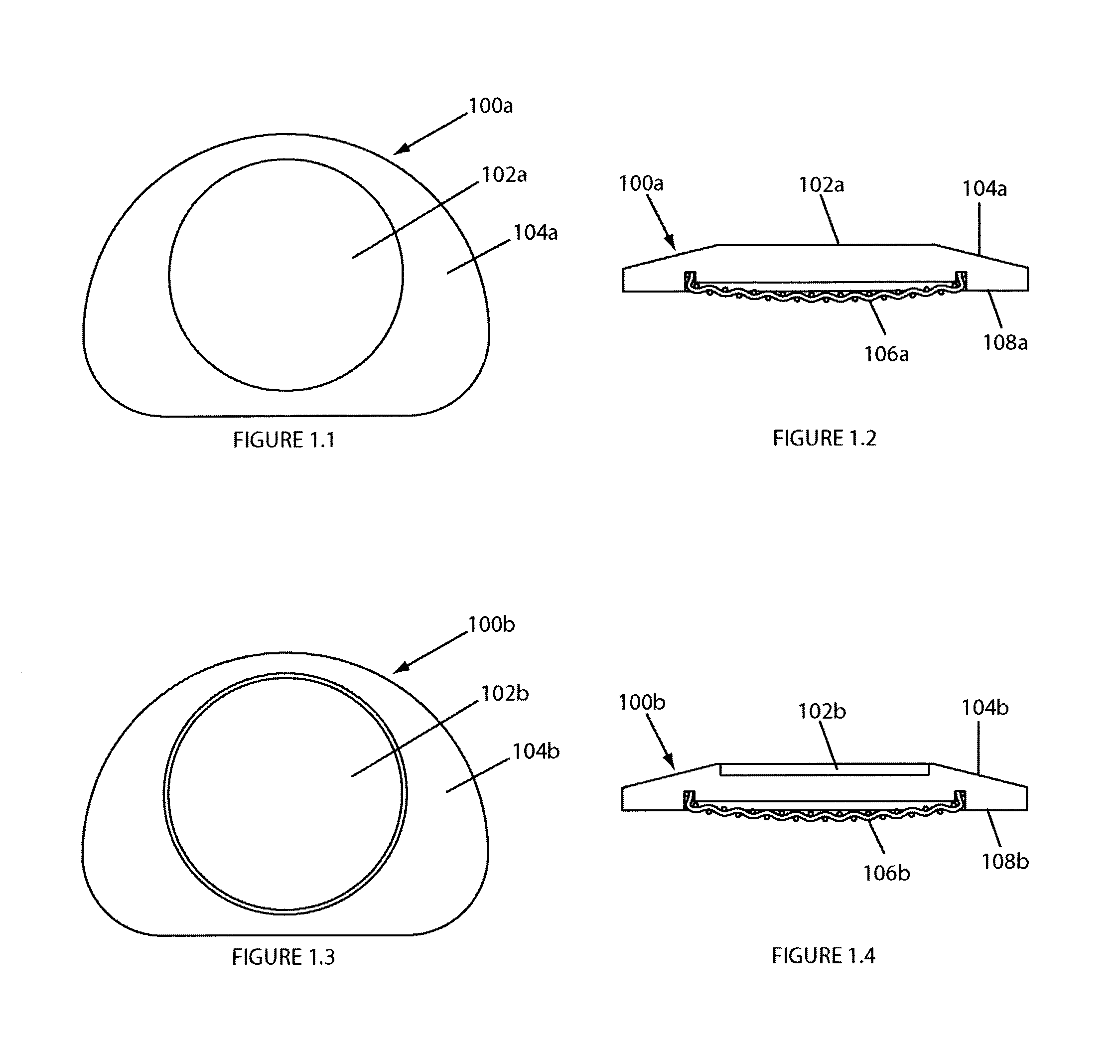
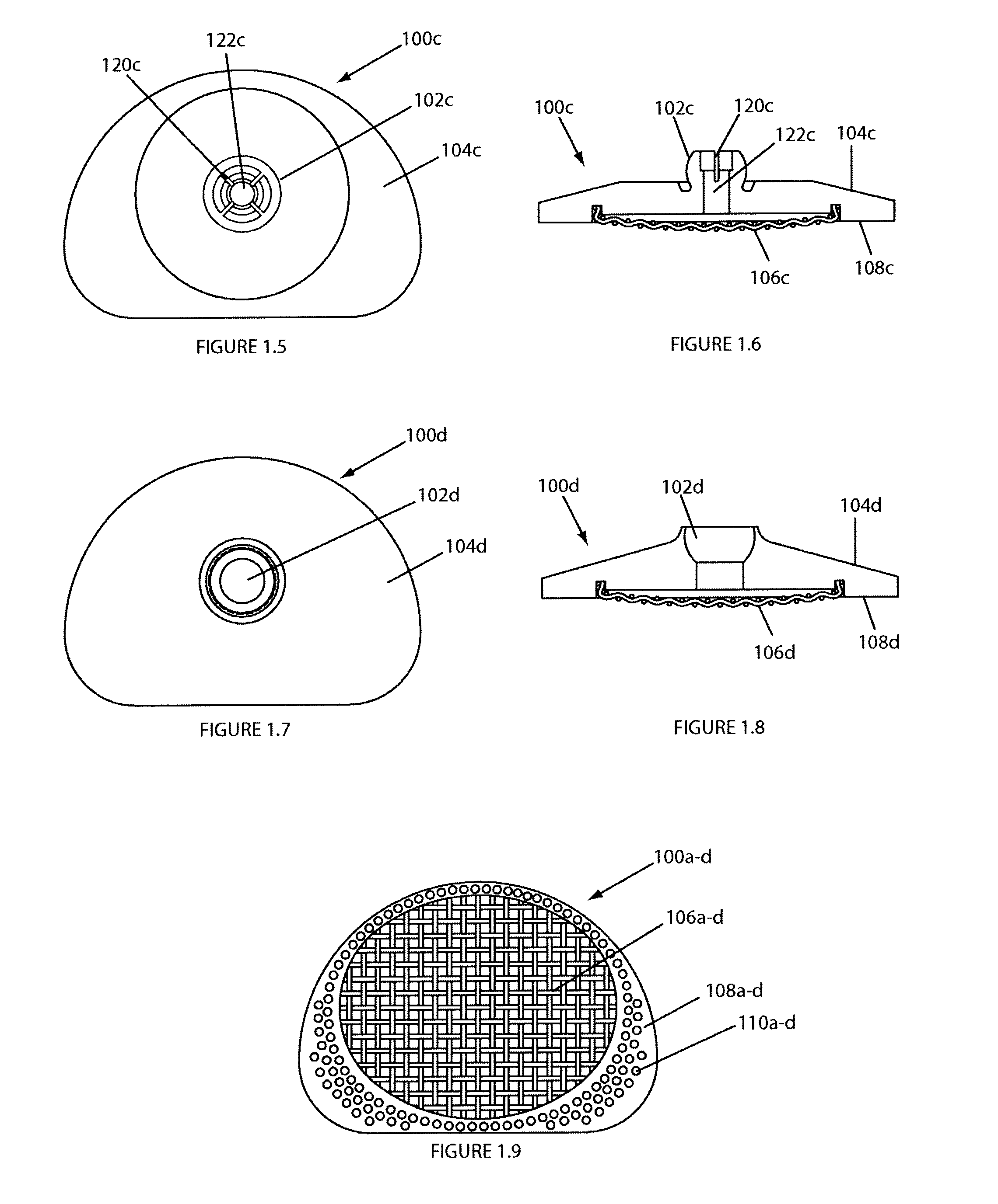
[0095]Referring now to FIGS. 1.1 through 1.9, various embodiments of plates of the invention for use in an artificial disc of the invention are shown in bottom plan views (FIGS. 1.1, 1.3, 1.5 and 1.7), side cutaway views (where cross-sectional areas and surfaces viewable behind them are shown) (FIGS. 1.2, 1.4, 1.6 and 1.8), and a top plan view (FIG. 1.9)....


PUM

PropertyMeasurementUnit
Forceaaaaaaaaaa

Abstract

An artificial disc having a pair of opposing plates for seating against opposing vertebral bone surfaces, separated by a spider spring having a plurality of spring arms extending radially from a central hub. Various spring arm embodiments disclosed include spring arms that are straight, bowed, grooved, wavy, thinning, or thickening; and spring arms with parallel sides, radially outwardly diverging sides, or radially outwardly diverging and curving sides. Various spider spring embodiments disclosed include spider springs with central hubs that are solid, bored, have curvate sockets, or have semispherical protuberances. Various plate embodiments disclosed include plates having, on inwardly facing surfaces, a curvate socket, a semispherical protuberance, a circular recess, or a flat surface. The spider springs are disposable between the plates, through various disclosed couplings, so that the plates compress, rotate and angulate freely relative to one another, enabling the artificial disc to mimic a healthy natural intervertebral disc.

Description

FIELD OF THE INVENTION[0001]This invention relates generally to a spinal implant assembly for implantation into the intervertebral space between adjacent vertebral bones to simultaneously provide stabilization and continued flexibility and proper anatomical motion, and more specifically to such a device that utilizes a spider spring force restoring element.BACKGROUND OF THE INVENTION[0002]The bones and connective tissue of an adult human spinal column consists of more than 20 discrete bones coupled sequentially to one another by a tri-joint complex that consists of an anterior disc and the two posterior facet joints, the anterior discs of adjacent bones being cushioned by cartilage spacers referred to as intervertebral discs. These more than 20 bones are anatomically categorized as being members of one of four classifications: cervical, thoracic, lumbar, or sacral. The cervical portion of the spine, which comprises the top of the spine, up to the base of the skull, includes the firs...

Claims


Application Information

Patent Timeline
IPC IPC(8): A61F2/44A61F2/00A61F2/30
CPCA61F2/4425A61F2/30742A61F2002/30171A61F2002/302A61F2002/30433A61F2002/30443A61F2002/30451A61F2002/30492A61F2002/30502A61F2002/30518A61F2002/30565A61F2002/30571A61F2002/30594A61F2002/30604A61F2002/30649A61F2002/30769A61F2002/30909A61F2002/3092A61F2002/443A61F2220/0025A61F2220/0041A61F2220/0058A61F2230/005A61F2230/0065A61F2310/00017A61F2310/00023A61F2310/00365A61F2002/305
Inventor RALPH, JAMES D.TATAR, STEPHENERRICO, JOSEPH P.
Owner HOWMEDICA OSTEONICS CORP
Why Eureka
Try Eureka