Magnetron for microwave ovens and method of forming same

a microwave oven and magnet technology, applied in the direction of transit-tube leading-in arrangements, electric/magnetic/electromagnetic heating, soldering apparatus, etc., can solve problems such as abrasion defects

Inactive Publication Date: 2006-10-17
SAMSUNG ELECTRONICS CO LTD
View PDF1 Cites 4 Cited by
  • Summary
  • Abstract
  • Description
  • Claims
  • Application Information

AI Technical Summary

Benefits of technology

[0012]Accordingly, it is an aspect of the present invention to provide a magnetron for microwave ovens, which has an anode to allow a manufacturing process thereof to be simplified, to allow the magnetron to have an optimal performance, and to prevent brazing defects attributable to insufficient blazing material from being inserted into the anode.
[0017]Each of the vanes may be plated with a brazing material to be brazed to one or more of the anode cylinder, of the strap rings and of the antenna, and the brazing material may have a predetermined plating depth to prevent insufficiency and excess thereof after brazing.

Problems solved by technology

However, the conventional method of manufacturing the anode 100 of the magnetron is problematic in that complicated brazing processes, in which the wire shaped brazing material is used and the strap rings 130 and the antenna 140 must be separately plated with the brazing material, must be performed to braze the component parts.
Furthermore, when the wire shaped brazing material is insufficiently inserted into joint portions, a brazing defect may be incurred.

Method used


Image

  • Magnetron for microwave ovens and method of forming same
  • Magnetron for microwave ovens and method of forming same
  • Magnetron for microwave ovens and method of forming same

Examples


Embodiment Construction

[0022]Reference will now be made in detail to the embodiment of the present invention, examples of which are illustrated in the accompanying drawings, wherein like reference numerals refer to like elements throughout.

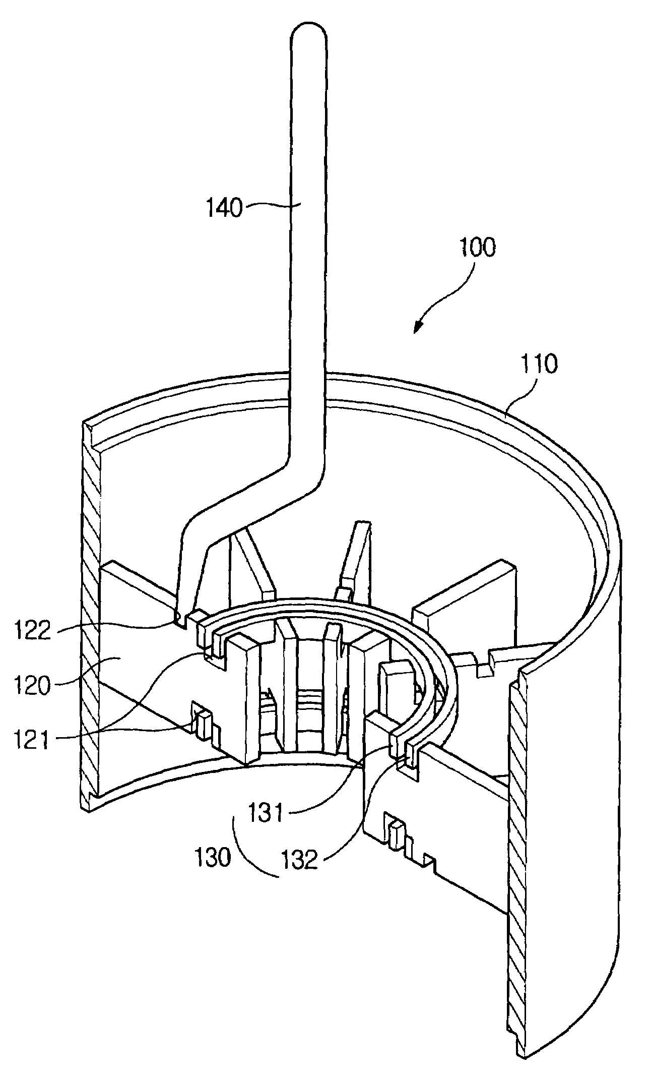
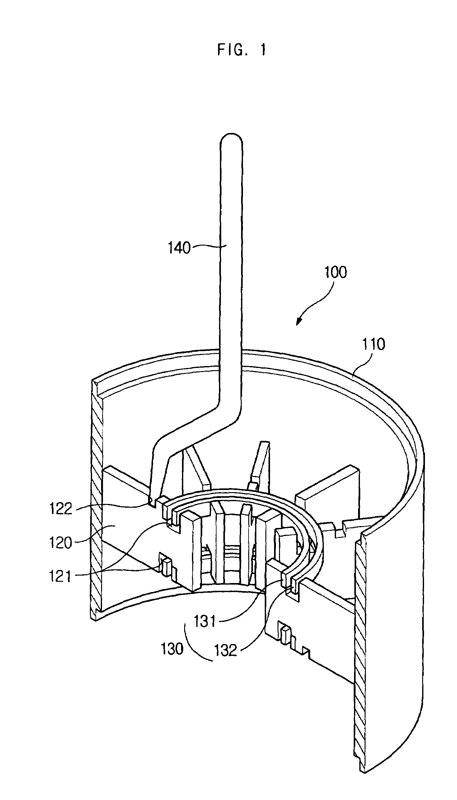
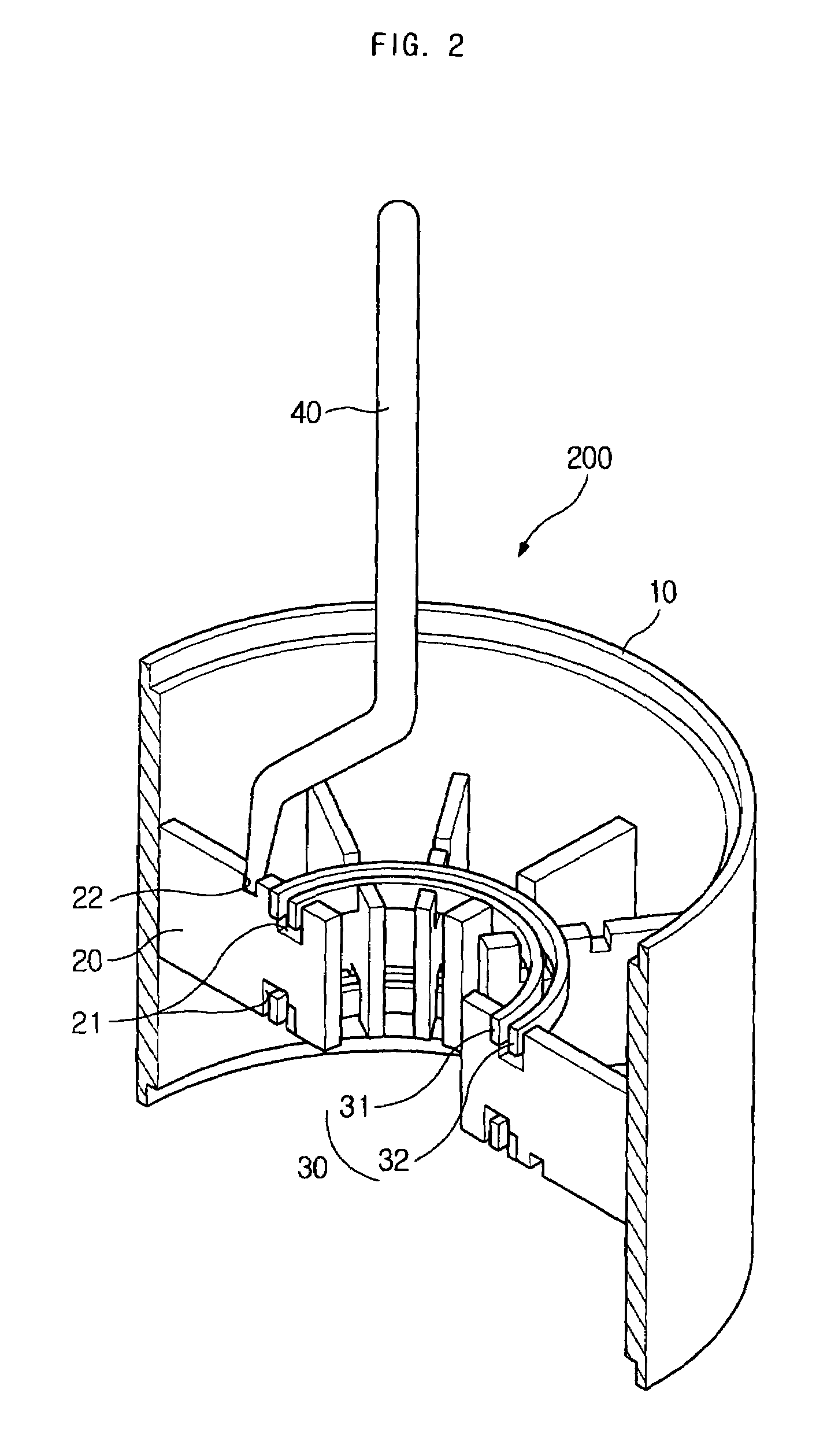
[0023]An anode 200 of a magnetron according to the present invention, as shown in FIG. 2, includes an anode cylinder 10, a plurality of plate-shaped vanes 20 radially arranged along an inside surface of the anode cylinder 10, one or more strap rings 30 to electrically connect the plurality of plate-shaped vanes 20 to each other, and an antenna 140 connected to one of the plurality of plate-shaped vanes 20 to radiate microwaves.

[0024]The anode cylinder 10, the plurality of plate-shaped vanes 20, the strap rings 30, and the antenna 40 are generally made of oxygen-free copper materials. The plurality of plate-shaped vanes 20 are formed in rectangular plate shapes, strap ring notches 21 are formed on a top and bottom of each of the vanes 20 to fasten the strap rings 30, and...


PUM

PropertyMeasurementUnit
depthaaaaaaaaaa
depthaaaaaaaaaa
depthaaaaaaaaaa

Abstract

A magnetron for microwave ovens includes an anode cylinder, a plurality of plate-shaped vanes radially arranged along an inside surface of the anode cylinder, one or more strap rings to electrically connect the plurality of plate-shaped vanes to each other, an antenna connected to one of the plurality of vanes to radiate microwaves generated from the plurality of vanes. Each of the vanes is plated with a brazing material to be brazed to one or more of the anode cylinder, the one or more strap rings and the antenna, and the brazing material has a plating depth of about 2.25 to 8 μm. The magnetron having the anode allows a manufacturing process of the anode to be simplified to reduce manufacturing time and equipment costs. Furthermore, the anode prevents brazing defects, and allows the magnetron to have an optimal performance.

Description

CROSS-REFERENCE TO RELATED APPLICATION[0001]This application claims the benefit of Korean Patent Application No. 2003-63002, filed Sep. 9, 2003 in the Korean Intellectual Property Office, the disclosure of which is incorporated herein by reference.BACKGROUND OF THE INVENTION[0002]1. Field of the Invention[0003]The present invention relates, in general, to a magnetron for microwave ovens and, more particularly, to an anode of a magnetron for microwave ovens, which allows the magnetron to have an optimal performance while causing a manufacturing process of the anode to be simplified and assembly of the anode to be easily performed.[0004]2. Description of the Related Art[0005]Generally, a magnetron for microwave ovens is a high frequency oscillation tube having a fundamental frequency at 2450 MHz. The magnetron includes a cathode and an anode coaxially arranged to form an electric field, and a pair of pole pieces to form magnetic fields above and below the cathode and the anode.[0006]A...

Claims


Application Information

Patent Timeline
Patent Type & Authority Patents(United States)
IPC IPC(8): H05B6/64H01J23/22B23K1/00H01J23/20H01J23/00H01J23/15H01J23/16H01J25/50H01J25/587
CPCH01J23/165H01J23/20H01J23/22H01J25/587H01J23/15
Inventor YANG, SUNG CHOL
Owner SAMSUNG ELECTRONICS CO LTD
Why Eureka
Try Eureka